Optical module, backlight control method and display device

An optical module and module technology, applied in optics, optical components, nonlinear optics, etc., can solve problems such as limited efficiency improvement, influence of efficiency backlight system design, and complex manufacturing methods, so as to improve display effect and realize local adjustment. Light, the effect of improving the utilization rate

Pending Publication Date: 2022-04-22
HUAWEI TECH CO LTD
View PDF0 Cites 2 Cited by
  • Summary
  • Abstract
  • Description
  • Claims
  • Application Information

AI Technical Summary

Problems solved by technology

However, the manufacturing method of this structure is relatively complicated, and the display effect of the panel using this technology is not good. The industry has not yet had a large-scale production capacity and method that can be commercialized.
Moreover, even if the technology overcomes the problem of mass production, it still has the same problem as the aforementioned multi-layer film stack design film material, that is, the light reused through this structure must return to the backlight system, and the efficiency is affected by the design of the backlight system , the efficiency is limited

Method used


Image

  • Optical module, backlight control method and display device
  • Optical module, backlight control method and display device
  • Optical module, backlight control method and display device

Examples


Embodiment Construction

[0054] The present application will be described in further detail below in conjunction with the accompanying drawings and embodiments. It should be understood that the specific implementation manners described here are only used to explain the present application, rather than to limit the present application.

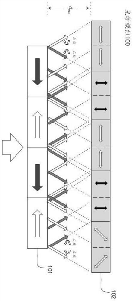
[0055] figure 1 It is a schematic structural diagram of an optical module provided in an embodiment of the present application, and the structure of the optical module 100 will be introduced below.

[0056] The optical module 100 includes a polarizing film 101 .

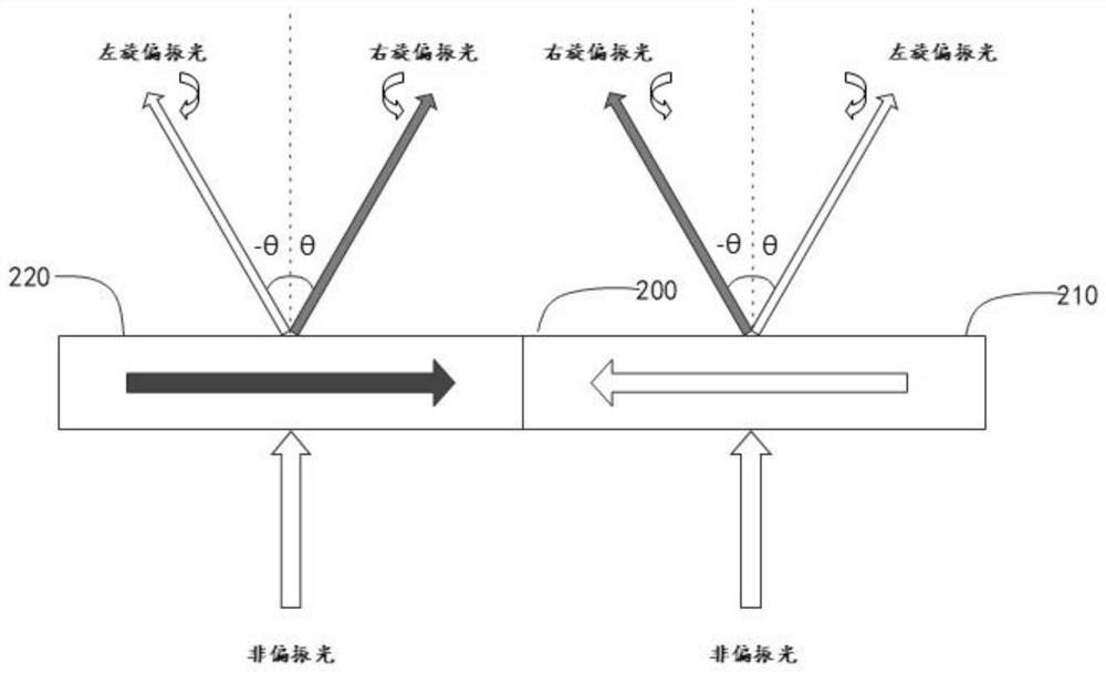
[0057] The embodiment of the present application uses the polarizing film 101 as a polarizing grating PG (Polarization Grating) structure for an exemplary introduction. It can be understood that the type of the polarizing film 101 is not limited to the PG structure, and can also be other types that can make the incident natural light realize left-handed The structure of separation from right-handed polarize...


PUM


Abstract

The invention provides an optical module comprising a polarizing film used for converting incident light into first polarized light with a first polarization state and second polarized light with a second polarization state; the phase delay layer is used for converting the first polarized light and the second polarized light into third polarized light comprising a third polarization state and fourth polarized light comprising a fourth polarization state; the first polarization state is different from the second polarization state; the phase retardation layer includes a control layer including one or more control elements. The optical module can be used for the display device. According to the technical scheme, the display effect of the display device can be improved, the utilization rate of effective polarized light of the backlight module is increased, and then the power consumption of the display device is reduced.

Description

technical field [0001] The present application relates to the display field, in particular to an optical module, a backlight control method and a display device. Background technique [0002] In a liquid crystal display device, in order to control the deflection of transmitted light through the liquid crystal layer in the liquid crystal panel, it is necessary to modulate the natural light generated by the backlight system to convert it into polarized light. Usually, a polarizer is placed between the liquid crystal panel and the backlight module, so that the natural light of the backlight module is modulated into polarized light and enters the liquid crystal panel. However, since the polarizer absorbs polarized light in opposite directions, at least 50% of the light source is lost in the light emitted by the backlight system, which reduces the efficiency of the backlight module. [0003] In order to improve the utilization efficiency of the backlight source, some new optical...

Claims


Application Information

Patent Timeline
Patent Type & Authority Applications(China)
IPC IPC(8): G02F1/1335G02F1/13363G02F1/13357
CPCG02F1/133528G02F1/13363G02F1/133606G02B27/28G02B27/286G02B5/201G02F1/13362G02F1/133507G02F1/133567G02F2203/50G02F1/133601
Inventor 张译文赵晨项刘康仲
Owner HUAWEI TECH CO LTD
Why Eureka
Try Eureka