Bracket structure of battery energy storage device and battery energy storage device

A support structure and battery energy storage technology, which is applied in the direction of secondary batteries, structural parts, battery pack parts, etc., can solve the problems of large temperature difference, large air volume difference, multiple energy sources, etc., and achieve low energy consumption, stable temperature, The effect of ensuring safety

Pending Publication Date: 2022-04-22
ZHUHAI GUANGTONG AUTOMOBILE +1
View PDF0 Cites 1 Cited by
  • Summary
  • Abstract
  • Description
  • Claims
  • Application Information

AI Technical Summary

Problems solved by technology

[0005] First, air-conditioning and ventilation are used to control the temperature of the battery modules installed on the bracket structure 1. It is difficult to form a uniform air flow field in the confined space of the bracket structure 1, and the air volumes received by the battery modules located in different areas are relatively different. Large, resulting in uneven temperature distribution among the battery modules, large temperature difference, affecting the product performance and life of the battery module
[0006] Second, for each energy storage device, the air conditioner 5 and the ventilation pipeline 6 of the temperature control module 2 occupy a relatively large space, resulting in the battery module that can be installed in each energy storage device under certain space conditions. The smaller the number of groups, the less power can be stored
[0007] Third, the power consumption of the air conditioner 5 of the temperature control module 2 is large, and the temperature control module 2 needs to consume more energy under the long-term operation of the energy storage device
[0008] Fourth, the temperature control module 2 controls the temperature of the battery through ventilation, and the speed of influence and effect on the temperature of the battery module is relatively slow. When the temperature of the battery module changes, it cannot control the temperature change of the battery module in time. It will cause the temperature of the battery module to fluctuate within a certain range

Method used


Image

  • Bracket structure of battery energy storage device and battery energy storage device
  • Bracket structure of battery energy storage device and battery energy storage device
  • Bracket structure of battery energy storage device and battery energy storage device

Examples


Embodiment Construction

[0031] In order to make the purpose, technical solutions and advantages of the embodiments of the present invention clearer, the technical solutions in the embodiments of the present invention will be clearly and completely described below in conjunction with the drawings in the embodiments of the present invention. Obviously, the described embodiments It is a part of embodiments of the present invention, but not all embodiments. Based on the embodiments of the present invention, all other embodiments obtained by persons of ordinary skill in the art without making creative efforts belong to the protection scope of the present invention.

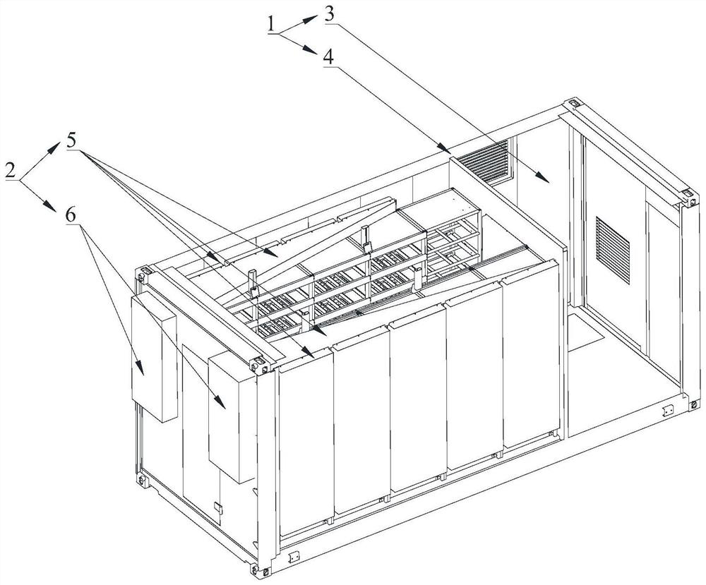
[0032] Embodiments of the bracket structure of the battery energy storage device and the battery energy storage device provided by the present invention will be described below with reference to the accompanying drawings.

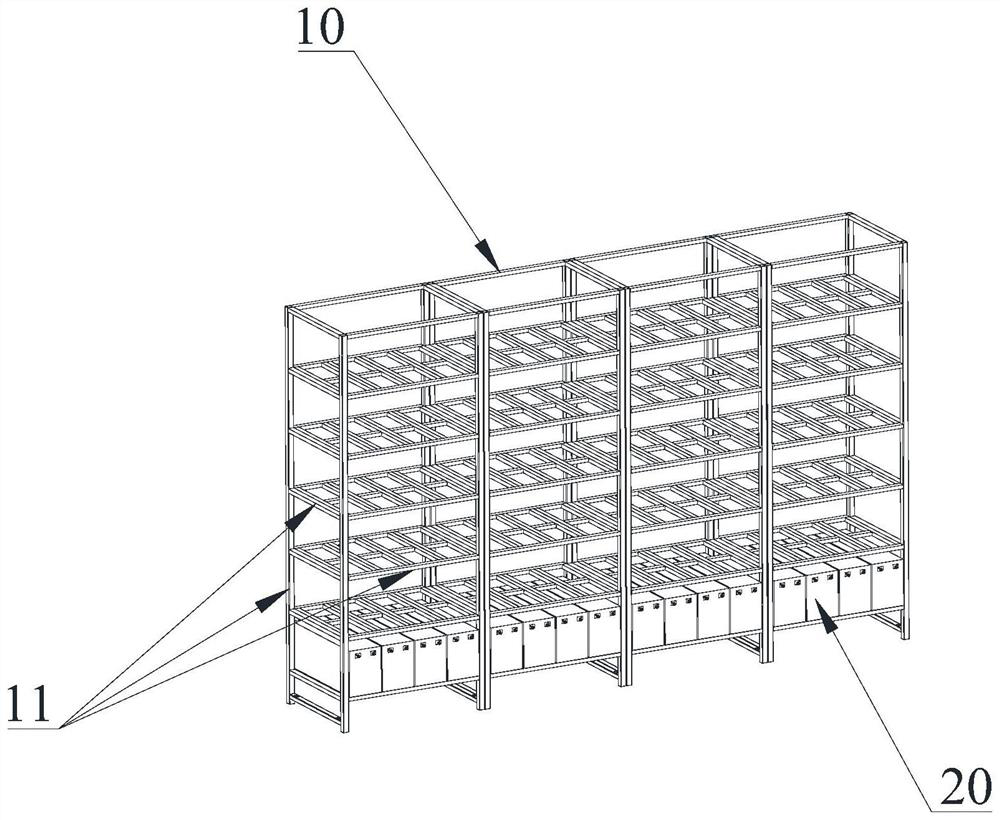
[0033] (1) Embodiment of the bracket structure of the battery energy storage device

[0034] The bracket structure 10 o...


PUM


Abstract

The invention relates to a support structure of a battery energy storage device and the battery energy storage device. The support structure is used for installing a battery module, a containing cavity is formed in the support structure, and the containing cavity is filled with a phase change material. The support structure is provided with a containing cavity, and the containing cavity is filled with phase change materials. Through the phase change material filled in the accommodating cavity, heat can be absorbed from the battery module when the temperature of the battery module is relatively high, and heat can be released to the battery module when the temperature of the battery module is relatively low, so that the temperature of the battery module is maintained, and the working performance of the battery module is ensured to be safe. Compared with the prior art, the support structure of the battery energy storage device can more uniformly control the temperature of each battery module in the battery energy storage device, more space can be provided for mounting more battery modules, the energy consumption is less, the temperature change range of the battery modules is smaller, and the temperature of the battery modules is more stable.

Description

technical field [0001] The invention relates to the technical field of energy storage devices, in particular to a support structure of a battery energy storage device and the battery energy storage device. Background technique [0002] In the energy supply of the future world, the proportion of fossil energy will continue to decrease, and the proportion of clean energy such as wind energy and solar energy will continue to increase. But clean energy also has some problems compared with fossil energy, such as clean energy usually must be converted into electrical energy before it can be used by people. At the same time, clean energy such as wind energy and solar energy is not stable enough to match well with changes in people's electricity load. Therefore, in the future, the role of energy storage devices will be very important. [0003] Such as figure 1 As shown, the existing energy storage device generally includes a support structure 1 , a battery module and a temperatur...

Claims


Application Information

Patent Timeline
Patent Type & Authority Applications(China)
IPC IPC(8): H01M10/613H01M10/655H01M10/6569H01M50/209
CPCH01M50/209H01M10/613H01M10/6569H01M10/655Y02E60/10
Inventor 荆振洋孙丰涛时高龙田士博
Owner ZHUHAI GUANGTONG AUTOMOBILE
Why Eureka
Try Eureka