Feeding equipment based on steel bar cut-off machine in house building

A technology of steel bar cutting machine and feeding equipment, which is applied in the field of steel bar cutting and can solve the problems of feeding difficulties and the like

Pending Publication Date: 2022-04-26
中国葛洲坝集团第三工程有限公司
View PDF0 Cites 0 Cited by
  • Summary
  • Abstract
  • Description
  • Claims
  • Application Information

AI Technical Summary

Problems solved by technology

[0004] The steel bar cutting machine mainly includes a fixed knife with a fixed position and a reciprocating moving knife, both of which are dislocated; when cutting steel bars, workers need to feed the steel bars between the fixed knife and the moving knife, and then move The knife moves toward the fixed knife under the drive of the power mechanism, and cuts off the steel bar; since the steel bar is usually long, after cutting a fixed length, the worker drags or pushes the subsequent steel bar again until the next cut It is difficult to feed when moving between the fixed knife and the moving knife

Method used


Image

  • Feeding equipment based on steel bar cut-off machine in house building
  • Feeding equipment based on steel bar cut-off machine in house building
  • Feeding equipment based on steel bar cut-off machine in house building

Examples


Embodiment Construction

[0064] The feeding equipment based on the steel bar cutting machine in housing construction proposed by the present invention will be further described in detail below in conjunction with the accompanying drawings and specific embodiments. The advantages and features of the present invention will become clearer from the following description. It should be noted that all the drawings are in a very simplified form and use imprecise scales, and are only used to facilitate and clearly assist the purpose of illustrating the embodiments of the present invention. The same or similar reference numerals in the drawings represent the same or similar components.

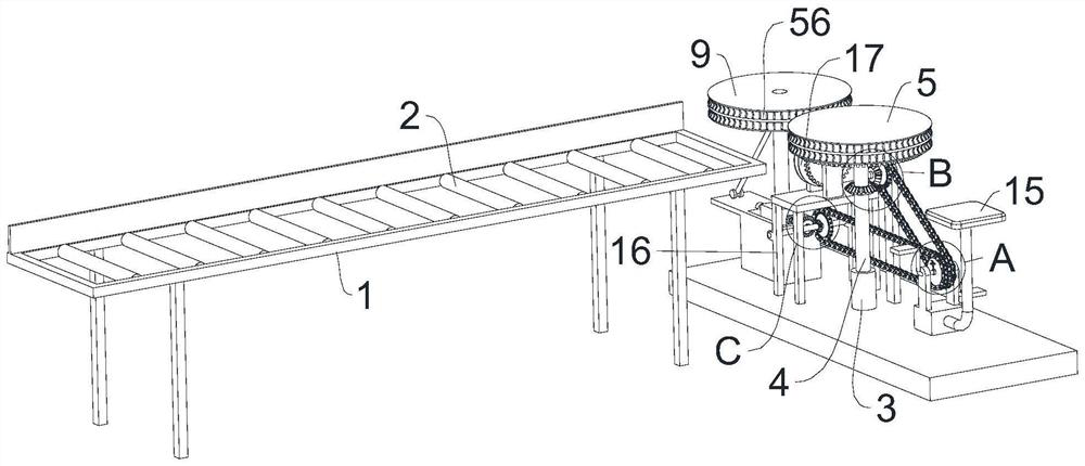
[0065] A kind of feeding equipment based on the steel bar cutting machine in house construction of the present invention, such as Figure 1 to Figure 19 shown, including,

[0066] Discharge frame 1, the top of discharge frame 1 is horizontally provided with several discharge rollers 2, and the top of discharge roller 2 is hig...


PUM


Abstract

The invention provides feeding equipment based on a steel bar cutting machine in housing construction. The feeding equipment comprises a discharging frame, and a discharging roller is arranged at the top of the discharging frame; a supporting rod is arranged on the supporting column, and a driving feeding wheel is arranged at the top of the supporting rod; a movable block is arranged at the top of the supporting block, a movable rod is vertically arranged at the top of the movable block, and a driven feeding wheel is arranged at the top of the movable rod; a driving frame, a driving rod is horizontally and rotatably arranged on the driving frame, Z-shaped driving handles are fixedly arranged at the two ends of the driving rod, and driving plates are rotatably arranged at the free ends of the driving handles; a supporting seat plate is horizontally arranged at the top of the seat plate frame; the first transmission structure is used for driving the driving feeding wheel to rotate; and the second transmission structure is used for driving the driven feeding wheel to be close to or away from the driving feeding wheel. According to the feeding equipment based on the steel bar cutting machine in housing construction, feeding can be conducted easily.

Description

technical field [0001] The invention belongs to the technical field of steel bar cutting, in particular to a feeding device based on a steel bar cutting machine in Fangjian. Background technique [0002] A lot of equipment is needed in house construction, such as excavators, loaders, dump trucks, bulldozers, generators, tower cranes, truck cranes, pile drivers, rammers, drilling rigs, electric welding machines, steel machinery, concrete pumps, vibrators, etc. Tampers, water pumps, concrete mixers, mixing stations, concrete placing machines, mixers, electric saws, electric planers, testing instruments, measuring instruments. Among them, the steel bar cutting machine is one of the common equipment. [0003] The steel bar cutting machine is mainly used for the fixed-length cutting of steel bars in civil engineering, and is an indispensable equipment in the process of steel bar processing. Compared with other cutting equipment, it has the advantages of light weight, less energ...

Claims


Application Information

Patent Timeline
IPC IPC(8): B21F23/00
CPCB21F23/00Y02P70/10
Inventor 梁玉坤贺晟
Owner 中国葛洲坝集团第三工程有限公司
Why Eureka
Try Eureka