
Self-propelled drag suction type dredger drag head with automatic adjusting function

A trailing suction dredger, automatic adjustment technology, applied to mechanically driven excavators/dredgers, earth movers/shovels, construction, etc., to achieve anti-sedimentation, ensure durability, and improve efficiency

Active Publication Date: 2022-04-26
CHEC DREDGING
View PDF7 Cites 0 Cited by
  • Summary
  • Abstract
  • Description
  • Claims
  • Application Information

AI Technical Summary

Problems solved by technology

[0009] (1) The technical problem to be solved by the present invention is to use a new type of hob to destroy the integrity of the rock, provide a free surface for the subsequent rake teeth to break the rock, and reduce the excavation resistance of the rake teeth. However, due to the fixed position of the rake teeth, the The digging depth of the rake teeth is fixed. For the hard rock substrate, the hardness of the rock substrate is different and the coverage depth is different, resulting in different degrees of wear of the rake teeth. For the hard rock substrate, the excavation depth is too deep, which will easily lead to the wear of the rake teeth and reduce the service life; The point crushing mechanism of the rock bottom cannot guarantee the durable rock breaking of the hob; the sedimentation of the broken rock bottom causes the mud pump to absorb too much river water, resulting in a reduction in the absorption efficiency of silt and rock bottom. Conducive to improving the efficiency of dredging operations

Method used


Image

  • Self-propelled drag suction type dredger drag head with automatic adjusting function
  • Self-propelled drag suction type dredger drag head with automatic adjusting function
  • Self-propelled drag suction type dredger drag head with automatic adjusting function

Examples


Embodiment 1

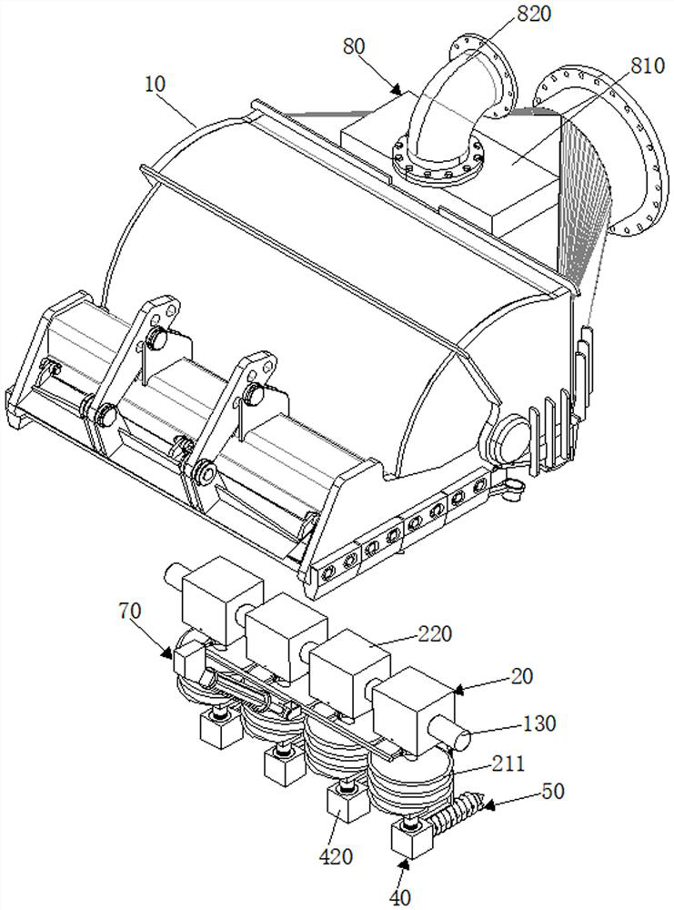
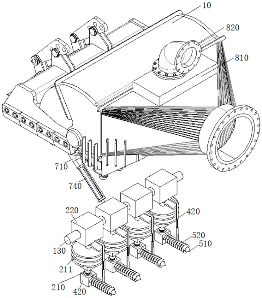
[0050] Such as figure 1 , figure 2 , image 3 , Figure 4 , Figure 5 , Figure 6 , Figure 7 and Figure 8 As shown, this embodiment proposes a self-propelled drag suction dredger drag head with an automatic adjustment function, including a drag head cover 10, a mounting column 110 installed at the front end of the drag head cover 10, and a detachable mounting column 110. The rake teeth 120 at the front end and the drive shaft 130 driven by the geared motor installed in the inner cavity of the rake head cover 10 also include:

[0051] The first transmission box 20 is equidistantly distributed on the outer wall of the drive shaft 130, and the transmission end of the first transmission box 20 is connected with a transmission rod 210;

[0052] The first buffer part 30 is arranged in the middle section of the transmission rod 210. In this embodiment, the first buffer part 30 divides the transmission rod 210 into two sections, specifically a telescopic rod and a sleeve con...

Embodiment 2

[0068] The scheme in embodiment 1 is further introduced below in combination with specific working methods, see the following description for details:

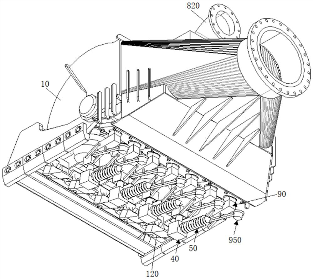
[0069] Such as figure 1 , figure 2 , image 3 , Figure 4 , Figure 9 and Figure 10 As shown, as a preferred embodiment, on the basis of the above method, further, the high-pressure water supply assembly 80 includes a water tank 810 installed in the rake head cover 10 and a water tank 810 installed on the top of the rake head cover 10 and communicated with the water inlet of the water tank 810 The high pressure flushing water pipeline 820.

[0070] The intermittent spray assembly 90 includes a sleeve 910 connected to the water outlet of the water tank 810, a sleeve rod 920 slidingly connected with the sleeve 910, a compression spring 930 sleeved on the sleeve rod 920 and placed in the rod section of the inner chamber of the sleeve 910, and set in the sleeve The pressure relief port on the outer wall of 910, the spray p...

Embodiment 3

[0073] The scheme in embodiment 2 is further introduced below in conjunction with specific working methods, see the following description for details:

[0074] Such as Figure 9 , Figure 10 As shown, as a preferred embodiment, on the basis of the above method, further, the intermittent hammer assembly 950 includes a connecting rod 951 fixedly connected to the outer wall of the sleeve 910, and a hammer connected to the end of the sleeve rod 920 away from the sleeve 910 in rotation. The hammer shaft 952 and the hammer head 953 installed on the end of the hammer shaft 952 away from the sleeve rod 920, the end of the connecting rod 951 away from the sleeve 910 is movably connected with the middle section of the hammer shaft 952;

[0075] When in use: through intermittent reciprocating expansion and contraction of the sleeve rod 920 on the intermittent injection assembly 90, the reciprocating swing of the hammer shaft 952 is realized, and then the intermittent hammering of the ha...


PUM


Abstract

The invention relates to a self-propelled drag suction dredger drag head with an automatic adjusting function, which comprises a drag head cover, a mounting column mounted at the front end of the drag head cover, rake teeth detachably mounted at the front end of the mounting column, and a driving shaft mounted in an inner cavity of the drag head cover and driven by a speed reducing motor, and further comprises first transmission boxes distributed on the outer wall of the driving shaft at equal intervals, the transmission end of the first transmission box is connected with a transmission rod; the first buffer part is arranged at the middle section of the transmission rod; the second transmission box is connected to the end, away from the first transmission box, of the transmission rod, and a limiting telescopic frame is connected between the first transmission box and the second transmission box; the slotting mechanism is connected to the transmission end of the second transmission box; the second buffer part is arranged at the middle section of the mounting column; the soil breaking stability of the slotting mechanism is effectively reduced, the service life of the slotting mechanism is guaranteed, meanwhile, deposition of broken rock substrates is effectively prevented, the proportion of sludge sucked by a sludge pump to the broken substrates is increased, and then the dredging operation efficiency is improved.

Description

technical field [0001] The invention relates to a self-propelled drag suction dredger drag head with an automatic adjustment function, belonging to the technical field of dredging engineering equipment. Background technique [0002] With the rapid development of my country's shipping industry and the vigorous development of infrastructure projects such as ports and waterways, the domestic demand for dredging ships is increasing. Trailing suction dredger is the most commonly used dredging ship in dredging projects. It has strong wind and wave resistance, little interference to shipping, large dredging depth, and unlimited transportation distance. It is suitable for land reclamation and large ports for deep water and long-distance operations. Waterway construction and maintenance projects. At present, the working mode of the trailing suction dredger is to dredge while sailing, and a drag head is respectively installed on both sides of the ship. When the dredger is sailing, i...

Claims


Application Information

Patent Timeline
IPC IPC(8): E02F3/88E02F3/92E02F5/28
CPCE02F3/885E02F3/9218E02F3/9225E02F3/9293E02F5/28
Inventor 李夏朱霖张戟薛海兵杨春雷李晟周滢童荣彬周丙浩
Owner CHEC DREDGING
Learn More