Intelligent crimping device for strain clamp

A technology of crimping device and tension clamp, which is applied in the direction of connection, line/collector parts, electrical components, etc., can solve the problem of poor bending degree of crimping of strain-resistant wires, long crimping guide rail length, and restrictions on aerial work platforms And crimping machine weight and other issues, to improve the quality of crimping, improve the effect of straightness

Pending Publication Date: 2022-04-26
BEIHAI POWER SUPPLY BUREAU OF GUANGXI GRID
View PDF0 Cites 0 Cited by
  • Summary
  • Abstract
  • Description
  • Claims
  • Application Information

AI Technical Summary

Problems solved by technology

During the crimping operation, the skill requirements of the operators are high, and the consistency of the crimping parameters such as the length of the stack mold, the crimping force and the pressure holding time cannot be guaranteed manually, which eventually leads to poor crimping bending of the tension clamp, and even Cannot guarantee wire grip requirements after crimping
[0004] 2) The aerial work platform is suspended on two anchor ropes, and the safety and stability requirements of the wire tightening system after the wire sag is fine-tuned limit the weight of the aerial work platform and the crimping machine. The existing suspension method of the aerial work platform , leading to a low safety factor of the tight line system and a greater risk of operation safety
[0005] 3) The aerial work platform is not equipped with guide rails. The main reasons are: ①The space of the aerial work platform is small, which is not conducive to the arrangement of crimping guide rails in the aerial work platform; The level of the platform causes the pressure clamp to slide to one end of the guide rail under the influence of gravity, which is not conducive to the high-altitude crimping operation of the tension clamp
[0006] ③ UHV project transmission lines are split conductors, generally 6-split or 8-split, and the split spacing is about 400mm to 500mm. When the line is tight, the same phase / pole conductors are laid flat in a plane, and the outermost sub-conductor clamps are crimped. There is an angle with the center line of the platform, and the length of the traditional crimping guide rail is long, and it is difficult to adjust the direction of the guide rail in the air

Method used


Image

  • Intelligent crimping device for strain clamp

Examples


Embodiment Construction

[0026] In order to better understand the present invention, the content of the present invention will be further described below in conjunction with the accompanying drawings and examples.

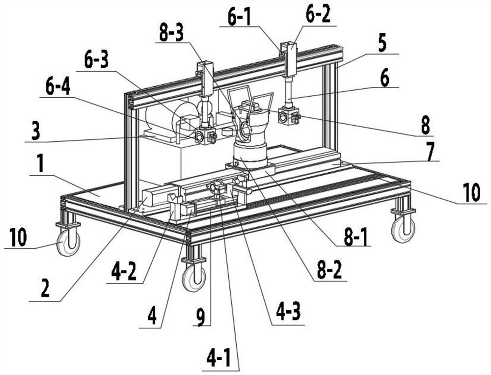
[0027] As shown in the figure, the present invention provides an intelligent crimping device for strain clamps, including a working platform 1, a crimping device 2 arranged in the middle of the working platform 1, and two crimping devices respectively arranged on the crimping device 2. side hydraulic pump 3 and cutting device 4;

[0028] The crimping device 2 includes a gantry bracket 5, two suspension clamping devices 6 that are slidably arranged on the top of the gantry bracket 5, a rolling screw slide rail device I7 that is arranged directly below the gantry bracket 5, and is arranged on the rolling screw The crimping pliers 8 on the slide rail device I7, the suspension clamping device 6 includes a sliding sleeve 6-1 sleeved on the gantry bracket 5, an adjustable connecting plate 6-2 ar...


PUM


Abstract

The invention provides an intelligent crimping device for a strain clamp. The intelligent crimping device comprises an operation platform, a crimping device arranged in the middle of the operation platform, a hydraulic pump and a cutting device, wherein the hydraulic pump and the cutting device are arranged on the two sides of the crimping device respectively. The crimping device comprises a gantry support, two suspension clamping devices arranged at the top end of the gantry support in a sliding mode, a rolling screw rod sliding rail device I arranged under the gantry support and crimping pliers arranged on the rolling screw rod sliding rail device I. Each suspension clamping device comprises a sliding sleeve arranged on the gantry support in a sleeving mode. The crimping clamp comprises a crimping guide rail, a sliding sleeve arranged on the crimping guide rail, an adjustable connecting plate arranged on the sliding sleeve, a clamping block fixedly arranged below the adjustable connecting plate, and a clamp arranged in the middle of the clamping block, the crimping clamp is driven by a ball screw to move to a to-be-crimped position of the strain clamp along the crimping guide rail, and the strain clamp is further fixed through a suspension clamping device. The crimping pliers can move along the direction of the crimping guide rail, the straightness of the crimping pipe after crimping is improved, and the crimping quality is improved.

Description

technical field [0001] The invention relates to power transmission and transformation construction technology, in particular to an intelligent crimping device for strain clamps. Background technique [0002] The crimping of strain clamps is mainly divided into crimping of steel anchors of strain clamps and crimping of aluminum tubes of strain clamps. The construction quality of strain clamp crimping directly affects the stability of the safe operation of the power grid. The crimping of the wire strain clamp is a high-altitude operation. The crimping machine needs to be placed on the high-altitude work platform, and the high-altitude work platform is suspended on the anchor rope, and the crimping operator completes the crimping operation on the high-altitude work platform. There are mainly the following problems in the traditional operation method: [0003] 1) The existing tension clamps are crimped manually with a light-duty crimping machine. The crimping position needs to...

Claims


Application Information

Patent Timeline
IPC IPC(8): H01R43/048
CPCH01R43/048
Inventor 秦绶坤蒋经魁万俊张德钦徐汉王玉贺夏鹏
Owner BEIHAI POWER SUPPLY BUREAU OF GUANGXI GRID
Why Eureka
Try Eureka