
Self-locking type packaging mechanical sealing structure

A mechanical seal and self-locking technology, which is applied in the direction of engine seal, mechanical equipment, engine components, etc., can solve the problems of mechanical expansion and tightness that cannot meet the requirements, safety hazards, shaft sleeve wear, etc., to ensure the sealing performance , Easy to install and disassemble, and the effect of compact sealing size

Pending Publication Date: 2022-04-29
安徽亚兰密封件股份有限公司
View PDF0 Cites 0 Cited by
  • Summary
  • Abstract
  • Description
  • Claims
  • Application Information

AI Technical Summary

Problems solved by technology

[0002] The shaft sleeve is a cylindrical mechanical part that is set on the rotating shaft. It is an integral part of the sliding bearing. During the long-term operation of the shaft sleeve, the journal surface is subjected to the extrusion force of the expansion sleeve and the combined mechanical force, which will cause it to appear. The problem of overall deformation, the diameter is elongated or reduced by 0.1mm-0.3mm, which will cause the mechanical expansion and tightening force to fail to meet the required tightening force, and there will be a fit gap between the shaft sleeve and the main shaft, which will further cause the wear of the shaft sleeve. Finally, when the equipment is in operation, there are certain potential safety hazards. Based on this, the present invention proposes a solution

Method used


Image

  • Self-locking type packaging mechanical sealing structure
  • Self-locking type packaging mechanical sealing structure
  • Self-locking type packaging mechanical sealing structure

Examples


Embodiment Construction

[0029] The following will clearly and completely describe the technical solutions in the embodiments of the present invention with reference to the accompanying drawings in the embodiments of the present invention. Obviously, the described embodiments are only some, not all, embodiments of the present invention. Based on the embodiments of the present invention, all other embodiments obtained by persons of ordinary skill in the art without creative efforts fall within the protection scope of the present invention.

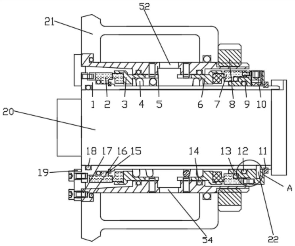
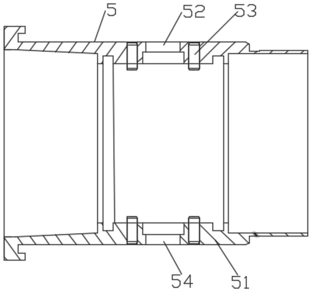
[0030] see figure 1 - Figure 5 As shown, the present invention is a self-locking mechanical seal structure, including a shaft sleeve assembly, a sealing mechanism and a fixing bracket 21 for fixing the sealing mechanism. The sealing mechanism is located between the fixing bracket 21 and the shaft sleeve assembly, and the shaft The sleeve assembly is located inside the fixed bracket 21, and one side of the fixed bracket 21 is provided with a lock nut 8 for connect...


PUM


Abstract

The invention discloses a self-locking type packaging mechanical sealing structure which comprises a shaft sleeve assembly, a sealing mechanism and a fixing support used for fixing the sealing mechanism, the sealing mechanism is located between the fixing support and the shaft sleeve assembly, and the shaft sleeve assembly is located in the fixing support. A locking nut used for connecting the shaft sleeve assembly with the sealing mechanism is arranged on one side of the fixing support, the outer surface of the shaft sleeve assembly is sleeved with a spring connected with the sealing mechanism, and the sealing mechanism comprises a sealing assembly with the outer surface making contact with the inner surface of the fixing support. A medium side static ring assembly and an atmosphere side static ring assembly are installed at the positions, close to the two sides, of the inner wall of the sealing assembly correspondingly. In the invention, the connection mode of the movable ring mounting seat and the shaft sleeve is innovatively designed by adopting a combination mode of positioning the transmission key and the shaft sleeve clamping ring, and the problem of radial deformation of the shaft sleeve is well solved, so that the shaft sleeve is sealed and is smoothly mounted and used.

Description

technical field [0001] The invention relates to the technical field of shaft sleeve seals, in particular to a self-locking cartridge mechanical seal structure. Background technique [0002] The shaft sleeve is a cylindrical mechanical part that is set on the rotating shaft. It is an integral part of the sliding bearing. During the long-term operation of the shaft sleeve, the journal surface is subjected to the extrusion force of the expansion sleeve and the combined mechanical force, which will cause it to appear. The problem of overall deformation, the diameter is elongated or reduced by 0.1mm-0.3mm, which will cause the mechanical expansion and tightening force to fail to meet the required tightening force, and there will be a fit gap between the shaft sleeve and the main shaft, which will further cause the wear of the shaft sleeve. Finally, when the equipment is in operation, there are certain potential safety hazards. Based on this, the present invention proposes a solut...

Claims


Application Information

Patent Timeline
Patent Type & Authority Applications(China)
IPC IPC(8): F16J15/34F16J15/38F16J15/40
CPCF16J15/3404F16J15/3452F16J15/3464F16J15/38F16J15/40
Inventor 黄炳喜杨浩刘东光黄亚男
Owner 安徽亚兰密封件股份有限公司
Learn More