Petroleum pipeline supporting device

A support device and oil pipeline technology, applied in the direction of pipeline supports, pipe components, pipes/pipe joints/fittings, etc., can solve the problems of equipment overall balance damage, reduce ground contact area, support device offset, etc., to achieve protection and Support, increase support, reduce the effect of shaking

Active Publication Date: 2022-04-29
海安发达石油仪器科技有限公司
View PDF10 Cites 0 Cited by
  • Summary
  • Abstract
  • Description
  • Claims
  • Application Information

AI Technical Summary

Problems solved by technology

[0005]Aiming at the deficiencies of the prior art, the present invention provides an oil pipeline support device, which solves the problem that the existing oil pipeline support The flow of PetroChina causes the support device to shift, resulting in the overall tilt of the equipment, reducing the contact area with the ground, prone to sinking and other phenomena, resulting in the destruction of the overall balance of the equipment

Method used


Image

  • Petroleum pipeline supporting device
  • Petroleum pipeline supporting device
  • Petroleum pipeline supporting device

Examples


Embodiment 1

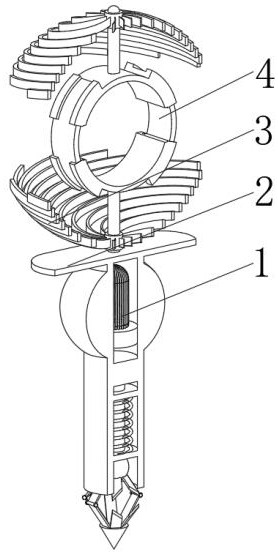
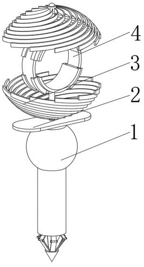
[0041] see Figure 1-6 , the present invention provides a technical solution: an oil pipeline support device, specifically comprising:

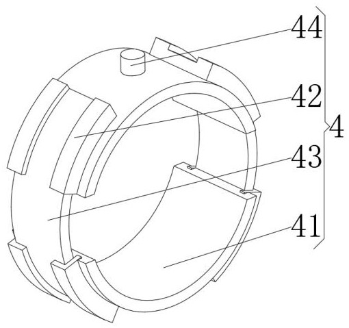
[0042] Fixed fork rod 1, the fixed fork rod 1 has a cylindrical rod, and a flat plate 2 installed on the top of the cylindrical rod, through the setting of the flat plate 2, the contact area between the equipment components and the ground is increased, and the support of the ground to the overall equipment is increased To prevent the equipment from sinking and tilting due to the weight change caused by the flow of oil in the pipeline, and to improve the fixed height and stability of the equipment to realize the protection and support of the oil pipeline. And the shielding shield 3 installed in the middle position of the top of the plane plate 2, and the pipeline fixing device 4 installed in the middle position of the inner cavity of the shielding shield 3, the pipeline fixing device 4 includes:

[0043] A fixed arc plate 41, the fixed arc pl...

Embodiment 2

[0056] see Figure 1-6 On the basis of Embodiment 1, the present invention provides a technical solution: a method for using an oil pipeline support device, comprising the following steps,

[0057] Step 1: The oil pipeline is placed between the fixed arc plates 41, and the locking arc plates 43 are installed between the L-shaped locking plates 42, and the fixed arc plates 41 are continuously pressed, so that the fixed arc plates 41 are mutually closed. Tighten, and use the locking teeth to lock the fixed arc plate 41 and the locking arc plate 43 against backward locking;

[0058] Step 2: Insert the fixed fork 1 into the ground as a whole to fix the whole device;

[0059] Step 3: After fixing the pipes and equipment as a whole, when the external environment is windy, the pipes and equipment are likely to shake under the influence of the wind, and the airflow drives the spherical arc-shaped bending plate 33 in the shielding shield 3 to rotate, making the spherical arc-shaped be...


PUM


Abstract

The invention discloses a petroleum pipeline supporting device which specifically comprises a fixing fork rod, a surface plate installed at the top of a cylindrical rod piece, a shielding protective cover installed in the middle of the top of the surface plate and a pipeline fixing device installed in the middle of an inner cavity of the shielding protective cover. L-shaped clamping plates are fixedly connected to the two sides of the outer surface of the arc-shaped plate body, locking arc plates are installed on the inner surfaces of the L-shaped clamping plates, and an installation column rod is installed on the outer surface of the arc-shaped plate body and located between the locking arc plates. The contact area between equipment components and the ground is increased through the arrangement of the surface plate, the supporting force of the ground on the whole equipment is increased, the situation that the equipment sinks and inclines due to the weight change generated by flowing of petroleum in the pipeline is avoided, the fixing height and stability of the equipment are improved, and protection and supporting of the petroleum pipeline are achieved.

Description

technical field [0001] The invention relates to the technical field of petroleum, in particular to a supporting device for petroleum pipelines. Background technique [0002] Petroleum, one of the main objects of geological exploration, is a viscous, dark brown liquid known as "industrial blood". There are oil reserves in some areas of the upper crust, and the main components are various alkanes, naphthenes, and aromatic hydrocarbons Petroleum is mainly used as fuel oil and gasoline, and is also a raw material for many chemical industry products, such as solutions, fertilizers, pesticides and plastics. [0003] During the use of the existing oil pipeline support device, the flow of oil in the oil pipeline will cause the support device to shift, resulting in the overall inclination of the equipment, reducing the contact area with the ground, and prone to subsidence and other phenomena, resulting in equipment failure. The overall balance is disrupted. Contents of the inventi...

Claims


Application Information

Patent Timeline
IPC IPC(8): F16L3/10F16L55/035
CPCF16L3/1066F16L55/035
Inventor 周爱勇周爱梅钱苏剑于磊
Owner 海安发达石油仪器科技有限公司
Why Eureka
Try Eureka