
Air conditioner with heat storage device

A heat storage device and air-conditioning technology, which is applied in the field of air-conditioning, can solve problems such as poor performance of the unit, discomfort of the human body, and low temperature of the indoor heat exchanger, and achieve the effects of simple structure, improved comfort, and improved indoor comfort

Active Publication Date: 2022-04-29
TSINGHUA UNIV
View PDF6 Cites 0 Cited by
  • Summary
  • Abstract
  • Description
  • Claims
  • Application Information

AI Technical Summary

Problems solved by technology

[0006] In view of the above problems, the purpose of the present invention is to provide an air conditioner with a heat storage device, which can not only solve the problem of the poor performance of the unit in the start-up stage of the existing room air conditioner, but also the low heating capacity and the low temperature of the indoor heat exchanger. The air supply makes the human body uncomfortable for a long time

Method used


Image

  • Air conditioner with heat storage device
  • Air conditioner with heat storage device
  • Air conditioner with heat storage device

Examples


Embodiment 1

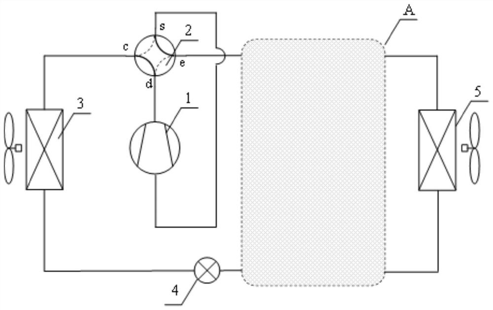
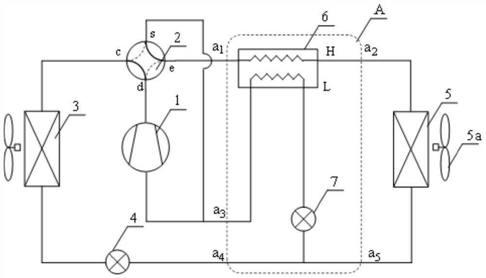
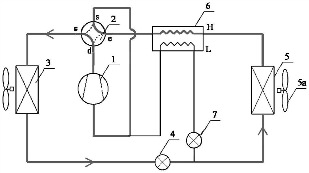
[0048] Such as figure 2 As shown, Embodiment 1 of the present invention provides an air conditioner with a heat storage device, including a compressor 1, a four-way valve 2, an outdoor heat exchanger 3, a first throttle valve 4, a heat storage device A and an indoor heat exchanger. Heater 5 and blower fan 5a. The heat storage device is configured such that the air conditioner includes a refrigeration circuit, a heating circuit, a heat storage circuit, a quick-start heating circuit, and a defrosting circuit. In the refrigeration circuit, heating circuit, heat storage circuit, and quick start heating circuit, the heat storage device is connected with the compressor 1, the four-way valve 2, the outdoor heat exchanger 3, the first throttle valve 4 and the indoor heat exchanger. The heaters 5 are connected in series to form a series unit. Therefore, the operating modes of the tandem units include cooling mode, heating mode, thermal storage mode, quick start mode and defrosting m...

Embodiment 2

[0057] Such as Figure 7 As shown, Embodiment 2 of the present invention provides an air conditioner with a heat storage device. The valve 4 and the indoor heat exchanger 5 are connected in parallel to form a parallel unit.

[0058] Specifically, the four-way valve 2 includes port d, port e, port c and port s. The thermal storage device is formed to include a first connection end b 1 , the second connection end b 2 , the third connection end b 3 and and the fourth connection terminal b 4 . The output end of the compressor 1 is connected to the port d, one end of the outdoor heat exchanger 3 is connected to the port c, and the other end is connected to one end of the indoor heat exchanger 5 through the first throttle valve 4 The s port is connected to the input end of the compressor 1, and the e port is connected to the other end of the indoor heat exchanger 5. The first connection end b of the heat storage device 1 Connected to the input end of the indoor heat exchange...


PUM


Abstract

The invention relates to an air conditioner with a heat storage device, which comprises a compressor, a four-way valve, an outdoor heat exchanger, a first throttle valve, the heat storage device and an indoor heat exchanger, and the heat storage device is configured to be connected with the indoor heat exchanger in parallel or in series; the heat storage device is configured to enable the air conditioner to be provided with a refrigerating circuit, a heating circuit, a heat storage circuit, a quick start heating circuit and a defrosting circuit. And in the series connection mode, the heat storage device comprises a second throttling valve and a heat accumulator, and the heat accumulator comprises a first heat storage coil pipe and a second heat storage coil pipe. In the parallel connection mode, the heat storage device comprises a three-way valve, a heat accumulator and a second throttling valve. On the basis of an original air conditioner structure, the heat accumulator is used for solving the problems that in the starting stage of an existing room air conditioner, unit performance is poor, heating capacity is low, the temperature of an indoor heat exchanger is low, and a human body feels uncomfortable for a long time due to air supply.

Description

technical field [0001] The invention relates to the field of air conditioners, in particular to an air conditioner with a heat storage device. Background technique [0002] Room air conditioners are an important means to solve the heating demand in non-centralized heating areas in the south and decentralized heating in rural areas in the north. However, when the air conditioner has high heating wind speed in winter, strong blowing sensation, uneven indoor, cold head and hot feet, etc., people complain widely. , especially the heating performance in the starting state is often unsatisfactory. When heating operation is required, the temperature of the indoor heat exchanger is relatively low just after starting up, and the air supply makes the human body feel uncomfortable. In addition, due to the low performance of the unit and the low heating capacity when it is turned on, there will be long-term indoor discomfort. [0003] CN201910219565.1 provides a defrosting method for ...

Claims


Application Information

Patent Timeline
Patent Type & Authority Applications(China)
IPC IPC(8): F24F11/30F24F11/42F24F11/65F24F11/84F24F11/875F24F11/88F24F11/89
CPCF24F11/30F24F11/42F24F11/65F24F11/84F24F11/875F24F11/88F24F11/89Y02E60/14
Inventor 石文星杨子旭肖寒松李无言王宝龙李先庭
Owner TSINGHUA UNIV
Learn More