
Graphical concept modeling method and device and computer equipment

A modeling method and graphical technology, applied in design optimization/simulation, geometric CAD, etc., can solve problems such as weak description, low efficiency, inability to describe model assumptions and related algorithms

Active Publication Date: 2022-04-29
HUNAN GAOZHI SCI & TECH CO LTD
View PDF5 Cites 4 Cited by
  • Summary
  • Abstract
  • Description
  • Claims
  • Application Information

AI Technical Summary

Problems solved by technology

[0003] However, at present, many experts and scholars at home and abroad have proposed a variety of different CM description methods for CM in the simulation modeling development process. The current entity-relationship (ER) method is suitable for establishing static models. It was originally used as It is proposed by the database model aided design tool, so the thinking is limited by the traditional database model (Database Model), which does not conform to people's normal thinking habits, lacks naturalness and directness; at the same time, when analyzing complex models, the description of the relationship between the models is not accurate. It is also impossible to describe the dynamic behavior characteristics between models, let alone the assumptions and related algorithms owned by the model. There is no corresponding specification for the description of objects and attributes in the object-role (ORM) method, which is prone to modeling Element defects, unclear description, ambiguity, etc. The process-oriented method is weak in describing the static characteristics (structure, relationship, attribute, function, etc.) of the system, which is not conducive to comprehensively grasping the needs of the entire simulation system. The concept of object-oriented method Modeling is prone to the problem of missing modeling elements. At the same time, this method is highly specialized, which is not conducive to the communication between domain experts and development technicians. These methods are inefficient, cannot control the complexity well, and display modeling elements Related information and other issues

Method used


Image

  • Graphical concept modeling method and device and computer equipment
  • Graphical concept modeling method and device and computer equipment
  • Graphical concept modeling method and device and computer equipment

Examples


Embodiment Construction

[0045] In order to make the purpose, technical solution and advantages of the present application clearer, the present application will be further described in detail below in conjunction with the accompanying drawings and embodiments. It should be understood that the specific embodiments described here are only used to explain the present application, and are not intended to limit the present application.

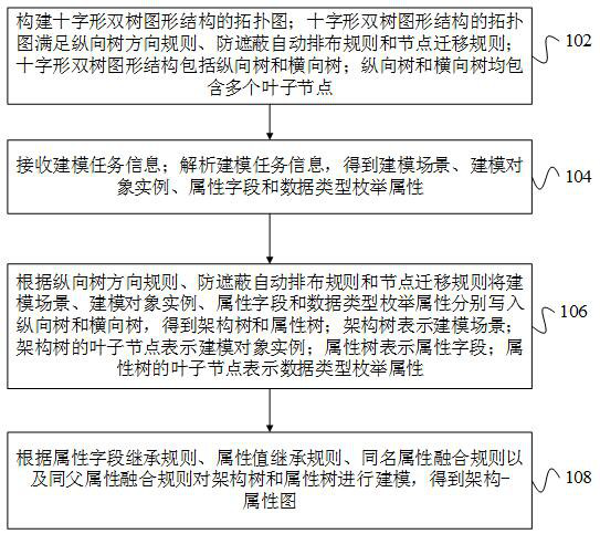
[0046] In one embodiment, such as figure 1 As shown, a graphical conceptual modeling method is provided, including the following steps:

[0047] Step 102, constructing the topological graph of the cross-shaped double-tree graph structure; the topological graph of the cross-shaped double-tree graph structure satisfies the vertical tree direction rules, anti-shading automatic arrangement rules and node migration rules; the cross-shaped double-tree graph structure includes vertical trees and Horizontal tree; both vertical and horizontal trees contain multiple leaf nodes.

...


PUM


Abstract

The invention relates to a graphical concept modeling method and device, computer equipment and a storage medium. The method comprises the following steps: constructing a topological graph of a cross-shaped dual-tree graphic structure; the cross-shaped double-tree graphic structure comprises a longitudinal tree and a transverse tree and is used for receiving modeling task information; analyzing the modeling task information to obtain a modeling scene, a modeling object instance, an attribute field and a data type enumeration attribute; respectively writing the modeling scene, the modeling object instance, the attribute field and the data type enumeration attribute into a longitudinal tree and a transverse tree according to a longitudinal tree direction rule, an anti-shielding automatic arrangement rule and a node migration rule to obtain an architecture tree and an attribute tree; and modeling the architecture tree and the attribute tree according to an attribute field inheriting rule, an attribute value inheriting rule, a homonymous attribute fusion rule and a same parent attribute fusion rule to obtain an architecture-attribute graph. By adopting the method, the simulation modeling efficiency can be improved.

Description

technical field [0001] The present application relates to the technical field of system modeling and simulation, in particular to a graphical conceptual modeling method, device, computer equipment and storage medium. Background technique [0002] With the development of simulation technology, modeling technology has emerged. Modeling is to abstract the data, process, and restrictions in reality into various models, while simulation is the execution of the model. With the continuous development of computer technology, modeling and simulation research, together with theoretical research and experimental research, has been widely concerned and developed as three main means of scientific research. Especially in the research of military system simulation, modeling and simulation technology has served many research fields such as strategy, tactics, tactics, training, experiment, analysis, and auxiliary decision-making, and the scope of application is still expanding, and the resea...

Claims


Application Information

Patent Timeline
Patent Type & Authority Applications(China)
IPC IPC(8): G06F30/20G06F30/12
CPCG06F30/20G06F30/12
Inventor 张聪张翼赵景张荣
Owner HUNAN GAOZHI SCI & TECH CO LTD
Learn More