Power battery module and electric power safety protection system

A power battery and power safety technology, applied in battery pack components, battery isolation from its environment, circuits, etc., can solve problems such as reducing the use safety of battery modules, reducing battery and air circulation, and unfavorable battery heat dissipation, etc. To achieve the effect of enhancing air circulation, improving use stability and reducing passiveness

Active Publication Date: 2022-04-29
GUILIN UNIV OF AEROSPACE TECH
View PDF8 Cites 0 Cited by
  • Summary
  • Abstract
  • Description
  • Claims
  • Application Information

AI Technical Summary

Problems solved by technology

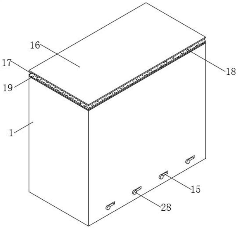
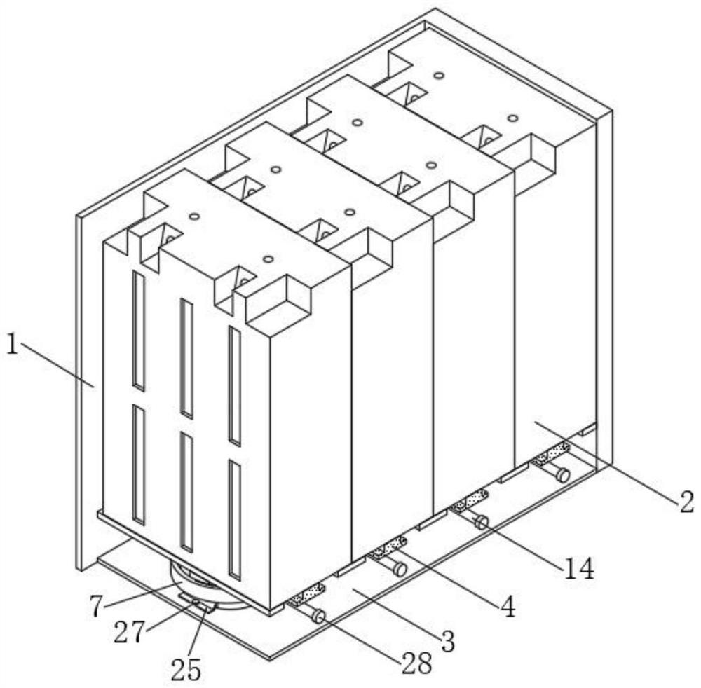
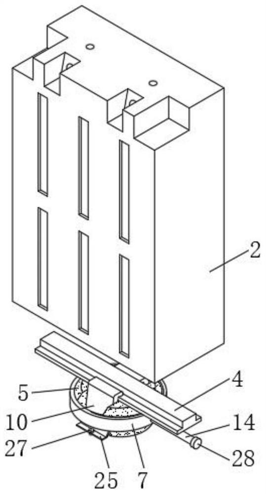
[0005] The purpose of the present invention is to provide a power battery module and an electric power safety protection system, which has the advantages of stable use and high safety factor, and solves the problem that when the existing power battery module is in use, the battery module is generally fixed by bolts. Installed in the inner cavity of the shell, so through this installation method, the bottom of the battery module will be closely attached to the inner wall of the shell, and then when the battery is running, the circulation between the battery and the air is reduced, which is not conducive to the damage to the battery. The heat is dissipated, which further increases the operating temperature of the battery and reduces the stability of its operation. Secondly, the battery module is large in size. If it encounters rainy weather and lacks protection for it, rainwater will easily enter the battery. Then reduce the problem of battery module use safety

Method used


Image

  • Power battery module and electric power safety protection system
  • Power battery module and electric power safety protection system
  • Power battery module and electric power safety protection system

Examples


Embodiment Construction

[0031] The technical solutions in the embodiments of the present invention will be clearly and completely described below in conjunction with the accompanying drawings in the embodiments of the present invention. In order to better understand the technical content of the present invention, specific embodiments are given and described as follows in conjunction with the accompanying drawings. Aspects of the invention are described in this disclosure with reference to the accompanying drawings, which show a number of illustrated embodiments. It should be appreciated that the various concepts and embodiments introduced above, as well as those concepts and implementations described in more detail below, can be implemented in any of numerous ways. Based on the embodiments of the present invention, all other embodiments obtained by persons of ordinary skill in the art without making creative efforts belong to the protection scope of the present invention.

[0032] as attached figure...


PUM


Abstract

The invention relates to the technical field of power battery modules, in particular to a power battery module and an electric power safety protection system.The power battery module comprises a shell and four power battery modules, the four power battery modules are located in an inner cavity of the shell and movably connected with the shell, a cavity is formed in the shell, and the power battery modules are arranged in the cavity. The bottom of the power battery module is fixedly connected with a connecting convex plate, the bottom of the connecting convex plate extends to an inner cavity of the cavity, the bottom of the inner cavity of the cavity is fixedly connected with a locking block, and an external thread is arranged above the surface of the locking block. In the actual use process, when the battery module is installed, the contact space between the bottom of the battery module and the shell is increased, the connection area between the power battery module and the shell is reduced, the heat dissipation space is reserved, the air circulation is enhanced, heat generated by the power battery module is dissipated, a stable use environment is created, and the service life of the battery module is prolonged. And thus, the use stability of the power battery module is improved.

Description

technical field [0001] The invention relates to the technical field of power battery modules, in particular to a power battery module and a power safety protection system. Background technique [0002] The publication number is a power battery module disclosed in CN108666451B. The power battery module has at least one battery cell and at least one electrical connection plate, and the electrical connection plate is floatingly connected to the pole of the battery cell for series or parallel connection between different battery cells. In the power battery module, the battery connection plate is connected to the pole of the battery cell in a floating connection, which not only simplifies the structure of the power battery module, but also facilitates installation and disassembly, thereby facilitating the secondary use of the power battery module; at the same time, it also improves Extend the service life of the power battery module. [0003] The problem to be solved is that wh...

Claims


Application Information

Patent Timeline
Patent Type & Authority Applications(China)
IPC IPC(8): H01M50/264H01M50/24
CPCH01M50/264H01M50/24Y02E60/10
Inventor 唐学帮董永妹
Owner GUILIN UNIV OF AEROSPACE TECH
Why Eureka
Try Eureka