Electrical automation power distribution cabinet safety emergency system and device

An electrical automation and emergency system technology, applied in the direction of circuit devices, measuring devices, electrical components, etc., can solve the problems of emergency personnel in safety accidents and failure to open, so as to avoid safety accidents, avoid current mismatch, and reduce the difficulty of wiring Effect

Active Publication Date: 2022-04-29
XIAN JIAOTONG UNIV CITY COLLEGE
View PDF11 Cites 0 Cited by
  • Summary
  • Abstract
  • Description
  • Claims
  • Application Information

AI Technical Summary

Problems solved by technology

[0004] The object of the present invention is to provide a safety emergency system and device for an electric automation power distribution cabinet to solve the problem that the electric automation power distribution cabinet proposed in the above background techn

Method used


Image

  • Electrical automation power distribution cabinet safety emergency system and device
  • Electrical automation power distribution cabinet safety emergency system and device
  • Electrical automation power distribution cabinet safety emergency system and device

Examples


Embodiment 1

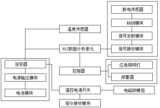
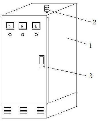
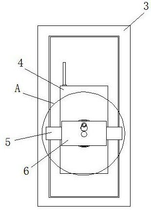
[0028] see Figure 1 to Figure 6 , the present invention provides a technical solution: an electric automation power distribution cabinet safety emergency system and device, including a PLC data analysis unit, a battery module, a power failure sensor 4 and an electromagnetic locking module 3, the electromagnetic locking module 3 is fixed to the distribution box On the electric cabinet body 1, the PLC data analysis unit and the battery module are located inside the power distribution cabinet body 1, the power failure sensor 4 is placed on the back of the electromagnetic locking module 3, the battery module is electrically connected to the power output module, and the power output module passes through It is electrically connected to an inverter, and through the designed inverter, the current output by the battery module is converted into a stable current used by the electromagnetic locking module 3, so as to avoid damage to the electromagnetic locking module 3 caused by current ...

Embodiment 2

[0032] see Figure 1 to Figure 6 , the present invention provides a technical solution: an electric automation power distribution cabinet safety emergency system and device, including a PLC data analysis unit, a battery module, a power failure sensor 4 and an electromagnetic locking module 3, the electromagnetic locking module 3 is fixed to the distribution box On the electric cabinet body 1, the PLC data analysis unit and the battery module are located inside the power distribution cabinet body 1, the power failure sensor 4 is placed on the back of the electromagnetic locking module 3, the battery module is electrically connected to the power output module, and the power output module passes through It is electrically connected to an inverter, and through the designed inverter, the current output by the battery module is converted into a stable current used by the electromagnetic locking module 3, so as to avoid damage to the electromagnetic locking module 3 caused by current ...


PUM


Abstract

The invention discloses an electrical automation power distribution cabinet safety emergency system and device, and the system comprises a PLC data analysis unit, a battery module, a power failure sensor, an electromagnetic lock module and a power distribution cabinet body, the electromagnetic lock module is fixed on the power distribution cabinet body, and the PLC data analysis unit and the battery module are located in the power distribution cabinet body. A turntable seat is fixed on the surface of one end of the power-off sensor, and a back frame is arranged on the turntable seat; through the designed power-off sensor, the battery module, the remote control power switch and the PLC data analysis unit, when the electromagnetic lock module does not supply power, the power-off sensor cannot sense an electric field generated by the electromagnetic lock module at the moment, a monitoring signal of the power-off sensor is transmitted to the PLC data analysis unit, so that the line state of the remote control power switch is in an on state, and the power-off sensor is in an off state. The battery module supplies power to the electromagnetic lock module emergently, so that the electromagnetic lock module reaches a normal working state, safety accidents caused by manual forcible entry in a traditional power failure state are effectively avoided, and safety emergency is achieved.

Description

technical field [0001] The invention belongs to the technical field of safety emergency systems for power distribution cabinets, and in particular relates to a safety emergency system and a device for electric automation power distribution cabinets. Background technique [0002] The electrical automation power distribution cabinet is a power supply equipment used in electrical automation production. There are various types of electrical components inside, so that the power distribution effect can be achieved through the cooperation between electrical components. The existing electrical automation power distribution During the working process of the cabinet, due to the excessive structure of the internal electrical components, the heat generated is too large, which makes the temperature in the power distribution cabinet too high, and the internal electrical components are easily damaged, which leads to frequent failures of the power distribution cabinet and is in a fault state...

Claims


Application Information

Patent Timeline
IPC IPC(8): H02J9/06G01K1/02H02B1/32
CPCH02J9/062H02J9/065H02B1/32G01K1/02
Inventor 张永超
Owner XIAN JIAOTONG UNIV CITY COLLEGE
Why Eureka
Try Eureka