
Intermediate bearing mounting structure of double-rotor turbofan engine

A technology of turbofan engine and installation structure, which is applied in the direction of engine components, machines/engines, mechanical equipment, etc., can solve the problems of difficulty in improving the radial stiffness of journals

Pending Publication Date: 2022-05-03
AECC SHENYANG ENGINE RES INST
View PDF0 Cites 0 Cited by
  • Summary
  • Abstract
  • Description
  • Claims
  • Application Information

AI Technical Summary

Problems solved by technology

[0005] The purpose of this application is to provide an intermediary bearing installation structure for a dual-rotor turbofan engine, to solve the problem that when the space for structural modification of the intermediary bearing in the prior art is limited, and the mating position of the intermediary bearing is relatively weak in the rotor journal, etc. Difficult to improve journal radial rigidity

Method used


Image

  • Intermediate bearing mounting structure of double-rotor turbofan engine
  • Intermediate bearing mounting structure of double-rotor turbofan engine
  • Intermediate bearing mounting structure of double-rotor turbofan engine

Examples


Embodiment Construction

[0014] In order to make the purpose, technical solution and advantages of the application more clear, the technical solution in the embodiment of the application will be described in more detail below in conjunction with the drawings in the embodiment of the application.

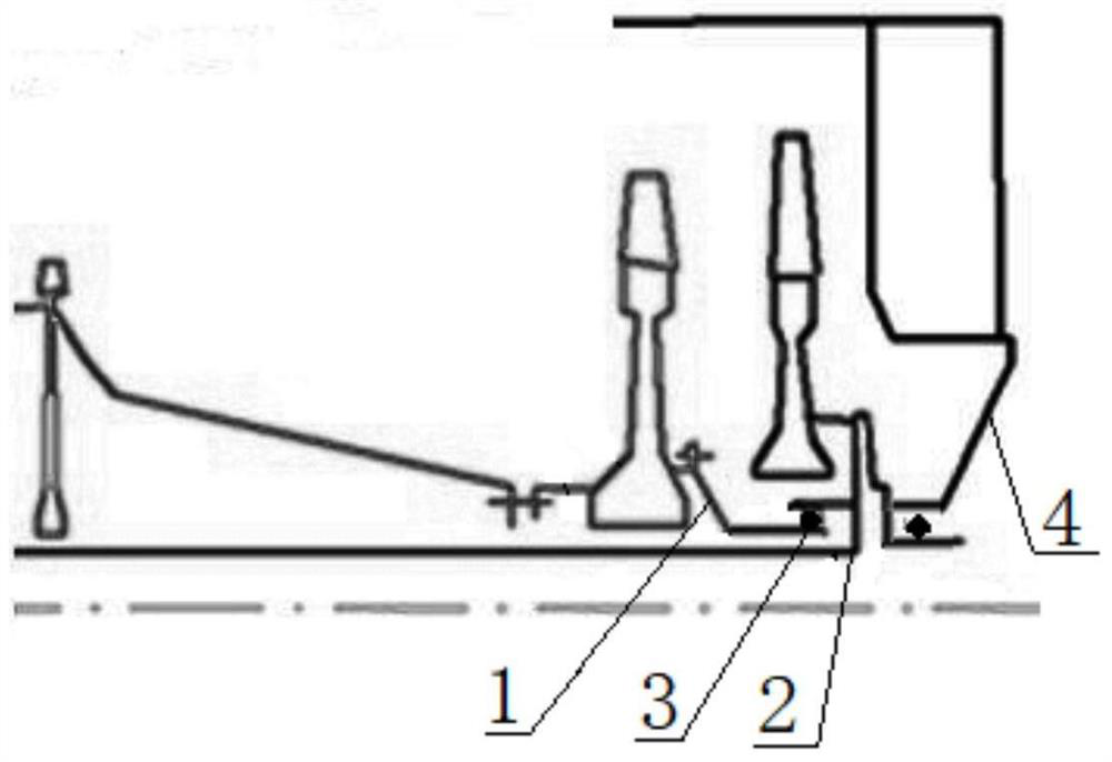
[0015] An intermediary bearing installation structure for a twin-rotor turbofan engine, such as figure 1 As shown, it includes high scroll 1 and low scroll 2, intermediary bearing 3 is provided between high scroll 1 and low scroll 2, intermediary bearing 3 is a roller bearing, and low scroll 2 is provided with a turbine rear machine Casing 4, the turbine rear case 4 is a stator, and a second roller bearing is provided between the turbine rear case 4 and the low scroll shaft 2, and the two roller bearings only bear radial force, not axial force Force, the radial force on the high scroll shaft 1 is transmitted to the low scroll shaft 2 through the intermediate bearing 3, and then the low scroll shaft 2 is tran...


PUM


Abstract

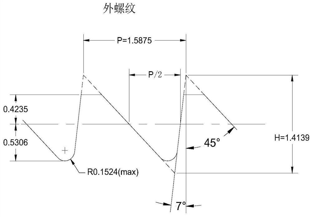
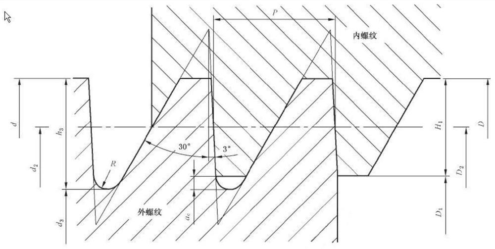
The invention belongs to the field of intermediary bearing mounting structures, and relates to a birotor turbofan engine intermediary bearing mounting structure which comprises a high turbine shaft and a low turbine shaft, an intermediary bearing is arranged between the high turbine shaft and the low turbine shaft and is a rolling rod bearing, the high turbine shaft is provided with external threads, and the low turbine shaft is provided with external threads. An internal thread matched with the external thread is arranged on the intermediate bearing inner ring compression nut, the internal thread and the external thread are both asymmetric tooth-shaped sawtooth threads, and the tooth-shaped angle of the asymmetric tooth-shaped sawtooth threads is 7 degrees / 45 degrees; when the intermediate bearing is stressed, the component force, parallel to the bearing tooth-shaped surface, of the asymmetric tooth-shaped sawtooth threads is small, and the high-turbine shaft rear shaft can complete force transmission without bearing large force, namely, the high-turbine shaft rear shaft can achieve stable radial force transmission without bearing large radial rigidity. The problem of insufficient structural space caused by purely increasing the radial thickness of the rear shaft in the traditional method is solved, and the stable interference fit relation between the bearing and the shaft is maintained in the working state of the engine.

Description

technical field [0001] The application belongs to the field of intermediary bearing installation structures, and in particular relates to an intermediary bearing installation structure for a dual-rotor turbofan engine. Background technique [0002] Compared with the symmetrical profile of the ordinary triangular thread, the zigzag thread is an asymmetric thread, which improves the bearing capacity along the axial direction of the thread through the asymmetric tooth structure. Compared with ordinary threads, the zigzag thread has the advantage that it can carry a particularly large axial load along the thread axis in a single direction, but it is not easy to cause fatigue damage to the thread teeth, so as to reduce the structural size and improve the reliability and safety of the connection. Purpose. [0003] At present, even if the serrated thread is used in aero-engines, the application position is limited to the position of the thrust bearing that bears a large axial load...

Claims


Application Information

Patent Timeline
Patent Type & Authority Applications(China)
IPC IPC(8): F01D25/16
CPCF01D25/16
Inventor 赵威孙博韩君曹茂国张西厂王东耿旭
Owner AECC SHENYANG ENGINE RES INST
Learn More