Clinical drainage device for oral surgery department
A technology of oral surgery and heating device, which is applied in the direction of suction devices, drug devices, other medical devices, etc., can solve the problems affecting the recovery of patients, unsatisfactory drainage effect, troublesome use, etc. reasonably simple effect
- Summary
- Abstract
- Description
- Claims
- Application Information
AI Technical Summary
Problems solved by technology
Method used
Image
Examples
Embodiment 1
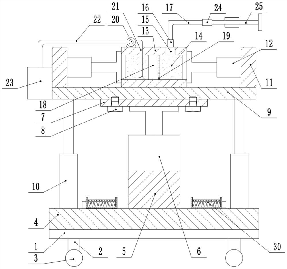
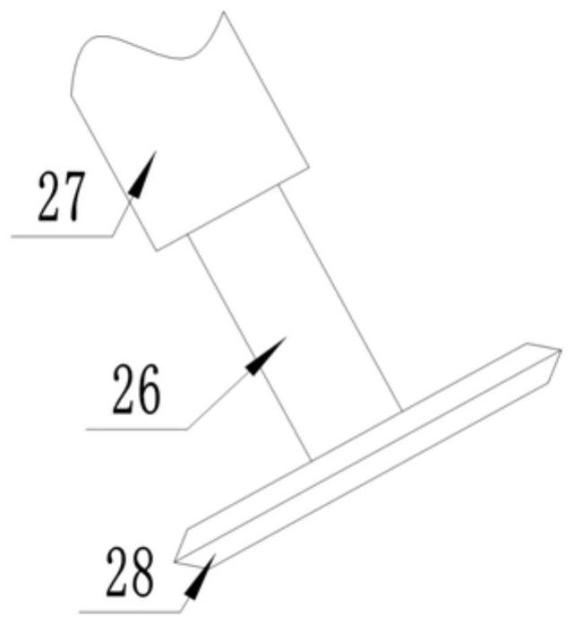
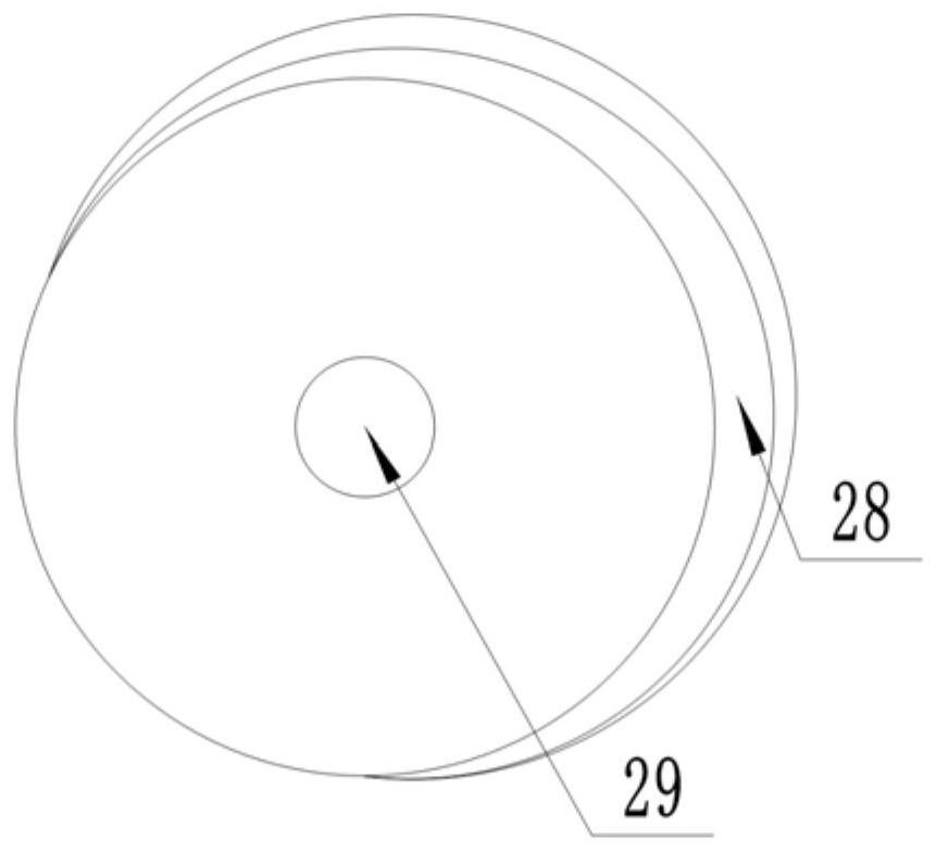
[0022] Such as Figure 1 to Figure 4 As shown, this specific embodiment adopts the following technical solutions: a clinical drainage device for oral surgery, including a base 1, supporting feet 2, universal wheels 3, a base plate 4, a fixing seat 5, a hydraulic cylinder 6, a mounting plate 7, and bolts 8 , fixed plate 9, telescopic rod 10, support plate 11, cylinder 12, cover plate 13, collection barrel 14, through hole 15, transparent tube 16, connecting tube 17, observation window 18, scale line 19, water pump 20, sewage inlet pipe 21. Sewage pipe 22, sewage storage tank 23, self-priming pump 24, suction device 25 and heating device 30; several supporting feet 2 are fixedly connected around the lower surface of the base 1, and the bottom of the supporting feet 2 is connected with ten thousand The steering wheel 3; the center of the upper end of the base plate 4 is fixedly connected with a fixed seat 5; the upper end of the fixed seat 5 is fixedly connected with a hydraulic ...
Embodiment 2
[0025] Such as Figure 1 to Figure 4 As shown, it includes base 1, supporting feet 2, universal wheels 3, bottom plate 4, fixed seat 5, hydraulic cylinder 6, mounting plate 7, bolts 8, fixing plate 9, telescopic rod 10, supporting plate 11, cylinder 12, cover Plate 13, collection barrel 14, through hole 15, transparent tube 16, connecting tube 17, observation window 18, scale line 19, water pump 20, sewage inlet pipe 21, sewage pipe 22, sewage storage tank 23, self-priming pump 24, suction The removal device 25 and the heating device 30; the lower surface of the base 1 is fixedly connected with several supporting feet 2, and the bottom end of the supporting feet 2 is connected with a universal wheel 3; the center of the upper end of the base plate 4 is fixedly connected with a fixed seat 5 The upper end of the fixed base 5 is fixedly connected with a hydraulic cylinder 6, and the output end of the hydraulic cylinder 6 is fixedly connected with a mounting plate 7; both sides of...
Embodiment 3
[0030] Such as Figure 1 to Figure 4As shown, it includes base 1, supporting feet 2, universal wheels 3, bottom plate 4, fixed seat 5, hydraulic cylinder 6, mounting plate 7, bolts 8, fixing plate 9, telescopic rod 10, supporting plate 11, cylinder 12, cover Plate 13, collection barrel 14, through hole 15, transparent tube 16, connecting tube 17, observation window 18, scale line 19, water pump 20, sewage inlet pipe 21, sewage pipe 22, sewage storage tank 23, self-priming pump 24, suction The removal device 25 and the heating device 30; the lower surface of the base 1 is fixedly connected with several supporting feet 2, and the bottom end of the supporting feet 2 is connected with a universal wheel 3; the center of the upper end of the base plate 4 is fixedly connected with a fixed seat 5 The upper end of the fixed base 5 is fixedly connected with a hydraulic cylinder 6, and the output end of the hydraulic cylinder 6 is fixedly connected with a mounting plate 7; both sides of ...
PUM
 Abstract
Description
Claims
Application Information
 - R&D
- Intellectual Property
- Life Sciences
- Materials
- Tech Scout
- Unparalleled Data Quality
- Higher Quality Content
- 60% Fewer Hallucinations
Browse by: Latest US Patents, China's latest patents, Technical Efficacy Thesaurus, Application Domain, Technology Topic, Popular Technical Reports.
© 2025 PatSnap. All rights reserved.Legal|Privacy policy|Modern Slavery Act Transparency Statement|Sitemap|About US| Contact US: help@patsnap.com


