Gray cloth cutting device

A cutting device and green cloth technology, which is applied in the cutting of textile materials, textile and paper making, fabric surface trimming, etc., can solve the problems of difficulty in the total thickness of green cloth, reduce processing efficiency, cutting error, etc., and achieve a simplified structure and diverse functions. , the effect of a wide range of applications

Active Publication Date: 2022-05-06
江苏松柏纺织品有限公司
View PDF8 Cites 0 Cited by
  • Summary
  • Abstract
  • Description
  • Claims
  • Application Information

AI Technical Summary

Problems solved by technology

[0004] However, there are still obvious defects in its use: 1. In the above-mentioned device, the cutting knife is located above the operating platform, and there is a large distance between the two. When the user determines the cutting position of the cloth, the It is necessary to compare and adjust the position of the cutting knife, but because the cutting knife is suspended above the fabric, the two cannot be in direct contact, so the position of the cutting knife tip is difficult to accurately align with the cutting point of the fabric, and cutting errors are prone to occur; 2. When the embryo The thickness of the cloth is different, or when cutting different quantities of multi-layer gray cloth at the same time, it is necessary to adjust the cutting depth flexibly, otherwise the cutting knife will pass through the gray cloth and damage the bottom plate, but the total thickness of the gray cloth is difficult to pass Direct observation with the naked eye, if additional measuring tools are used, the equipment will still be complicated, and the processing efficiency will be reduced, which will cause more inconvenience

Method used


Image

  • Gray cloth cutting device
  • Gray cloth cutting device
  • Gray cloth cutting device

Examples


Embodiment 1

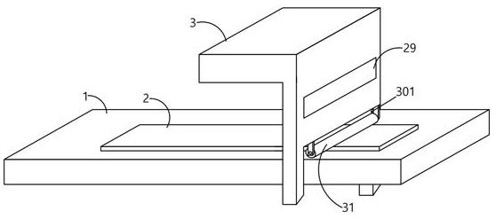
[0049] When in use, the gray cloth 2 is laid flat on the bottom plate 1. At this time, if the gray cloth 2 needs to be cut vertically, two positioning pins 4 can be taken, and the positioning pin tip 404 at the bottom of the positioning pins 4 can be inserted into the gray cloth. 2, the connecting line between the two positioning pins 4 forms a straight line, which is the line of the cutting position. Of course, for more accurate positioning, several positioning pins can also be added between the two positioning pins 4 at both ends. 4.

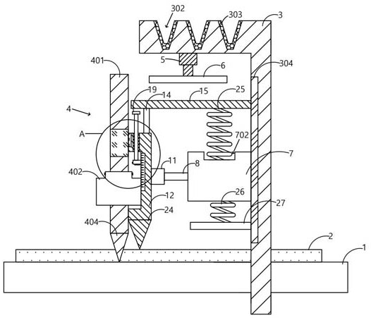
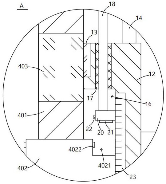
[0050] The L-shaped plate 3 as a whole can be driven and moved by an external power device, so that the cutting knife plate 12 is close to the positioning pin 4. At this time, the power supply of the miniature electromagnetic chuck 13 can be automatically or remotely opened, so that the miniature electromagnetic chuck 13 is energized to generate magnetism, resulting in The miniature electromagnetic chuck 13 is adsorbed and attached to the magn...

Embodiment 2

[0055] This embodiment is similar to Embodiment 1, the only difference is that in this embodiment, the gray cloth 2 can be cut obliquely. The two ends of the oblique cutting line, similarly, for more accurate positioning, several positioning pins 4 can also be added between the two positioning pins 4 at these two ends.

[0056] Then the whole L-shaped plate 3 is driven and moved by an external power device, so that the cutting blade plate 12 is close to the positioning pin 4. At this time, because the positioning pin 4 forms an oblique line, the cutting blade plate 12 is adsorbed by the miniature electromagnetic chuck 13. Also can tilt afterward, at this moment, the two adjusting rods 8 move to different degrees in the mounting groove 701, the adjusting rod 8 and the connecting block 11 are hinged by the rotating shaft 10, and the connecting block 11 and the cutting blade plate 12 are hinged. Hinged, so the position of the cutting knife plate 12 can be adjusted freely, thereby...


PUM


Abstract

The invention provides a gray cloth cutting device which is characterized in that gray cloth is placed on a bottom plate, and the bottom plate is clamped and embedded in an opening of an L-shaped plate; the positioning needle can be movably inserted into a positioning groove formed in the top of the L-shaped plate, the positioning needle comprises a positioning needle rod, a magnetic rod section is arranged between the positioning needle rod and the limiting part, and a positioning needle point is arranged at the bottom of the positioning needle rod; the mounting plate is connected with a cutting knife board through an angle adjusting structure, a pressure sensor is fixedly arranged at the bottom of the stopping block, a clamping block is fixedly arranged on the side face of the stopping block, and a cutting knife is fixedly arranged at the bottom of the cutting knife board. A flattening roller is hinged to the center shaft, and an adjusting spring is connected between the movable plate and the top wall of the top groove. The gray cloth cutting device is simple in overall structure, more diversified in function, capable of achieving more accurate positioning and cutting of gray cloth, flexible in operation and quite worthy of popularization.

Description

technical field [0001] The invention relates to the technical field of textile processing, in particular to a gray cloth cutting device. Background technique [0002] When the fabric gray cloth is produced as a finished product, the whole fabric needs to be cut, so that the fabric can be divided into individual individuals and then spliced. However, in the actual production process, the cutting of the gray cloth is generally done manually, and the cutting efficiency is relatively low. Low, after determining the cutting position of the gray cloth, it is necessary to compare and adjust the position of the cutting knife, which is prone to errors, making the manual cutting of the gray cloth less accurate and inconvenient to use. [0003] In the prior art, a pure polyester yarn knitted fabric cutting device with the publication number "CN212955882U" includes an operating platform, a cutting board and a supporting part are fixedly installed on the top of the operating platform, an...

Claims


Application Information

Patent Timeline
Patent Type & Authority Applications(China)
IPC IPC(8): D06H7/00D06C15/00
CPCD06H7/00D06C15/00
Inventor 徐建新
Owner 江苏松柏纺织品有限公司
Why Eureka
Try Eureka