Butt joint method of newly-built GIS bus and existing GIS bus and GIS bus system

A busbar system and busbar technology, applied in the direction of fully enclosed busbar devices, connections, cable joints, etc., can solve the problems of high cost, low operation efficiency, and low operation efficiency in the docking process, so as to improve efficiency, improve operation efficiency, and reduce connection The effect of times

Pending Publication Date: 2022-05-06
HENAN PINGZHI HIGH VOLTAGE SWITCHGEAR +2
View PDF7 Cites 0 Cited by
  • Summary
  • Abstract
  • Description
  • Claims
  • Application Information

AI Technical Summary

Problems solved by technology

[0005] The purpose of the present invention is to provide a GIS bus system to solve the problem of low operating efficiency in the docking process of the existing GIS bus system; at the same time, another purpose of the present invention is to provide a new GIS bus and the existing GIS bus docking method , to solve the problems of low operating efficiency and high cost of existing docking methods

Method used


Image

  • Butt joint method of newly-built GIS bus and existing GIS bus and GIS bus system
  • Butt joint method of newly-built GIS bus and existing GIS bus and GIS bus system
  • Butt joint method of newly-built GIS bus and existing GIS bus and GIS bus system

Examples


Embodiment 1

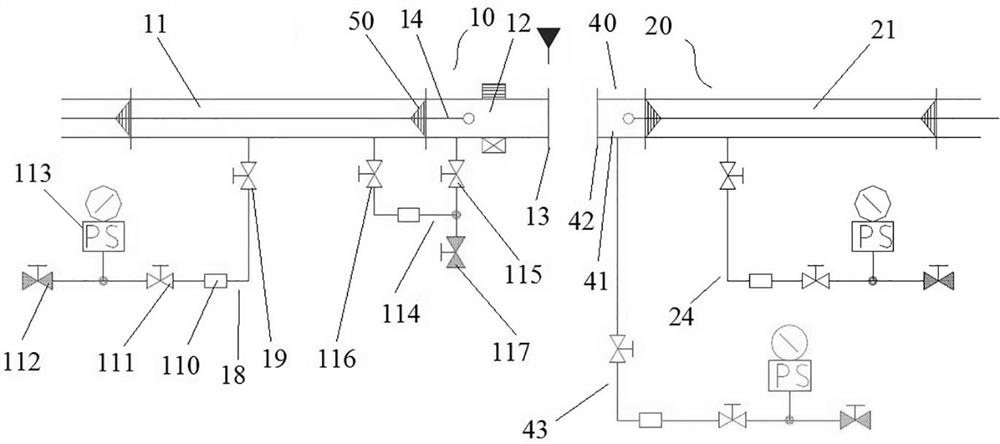
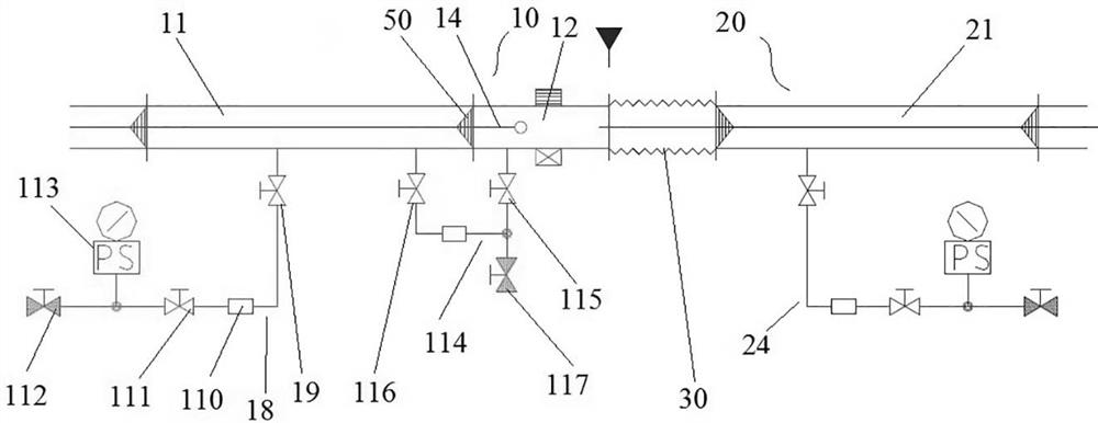
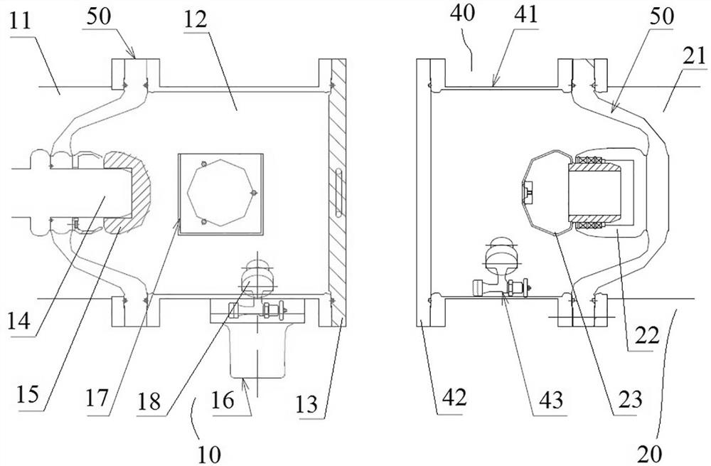
[0063] like figure 1 and figure 2 As shown, the GIS busbar system includes the existing GIS busbar 10, the new GIS busbar 20, the detachable busbar 30 and the test device 40, and the existing GIS busbar 10 and the new GIS busbar 20 are connected by figure 1 , figure 2 and Figure 5 Marking boundaries composed of triangles and straight lines in . Among them, the detachable bus bar 30 (such as figure 2 ) is used to connect between the new GIS bus 20 and the existing GIS bus 10 during docking, which is a structure in the prior art; the test device 40 is used to temporarily connect to the existing GIS bus 10 before the new GIS bus 20 is docked. On the transition bus 21 of the newly-built GIS bus 20, a test is carried out on the newly-built GIS bus 20.

[0064] Existing GIS busbar 10 includes reserved busbar 11, reserved joint barrel 12, reserved cover plate 13 and reserved joint 14 (for reserved joint 14 see Figure 4 and Figure 5 ), the left side of the reserved busbar...

Embodiment 2

[0088] The difference between this embodiment and Embodiment 1 is that in Embodiment 1, a communication pipeline is formed between the charging and deflation device on the reserved joint cylinder 12 and the reserved busbar, while in this embodiment, the reserved joint cylinder 12 The inflation and deflation device on the 12 is an independent inflation and deflation device.

Embodiment 3

[0090] The difference between this embodiment and Embodiment 1 is that, in Embodiment 1, the communication pipeline between the charging and deflation device on the reserved joint cylinder 12 and the reserved busbar includes two valves, while in this embodiment, There is only one valve and a corresponding pipeline for the communication pipeline between the inflation and deflation device on the reserved joint cylinder 12 and the reserved busbar.


PUM


Abstract

The invention relates to a butt joint method of a newly-built GIS bus and an existing GIS bus and a GIS bus system. The GIS bus system comprises an existing GIS bus, a newly-built GIS bus and a detachable bus; the existing GIS bus reserved joint cylinder is used for being connected to a reserved bus and is provided with a butt joint end which is in butt joint with a detachable bus and is communicated with the detachable bus. The reserved cover plate is used for blocking the butt joint end of the reserved joint cylinder, so that the reserved joint cylinder forms an independent closed air chamber; the reserved joint is arranged on the insulator at the butt joint of the reserved bus and the reserved joint cylinder, is positioned in the reserved joint cylinder and is used for connecting a corresponding central conductor; and an inflating and deflating device is arranged on the reserved joint cylinder. The reserved joint cylinder can be directly connected to the butt joint end of the reserved bus of the GIS when the existing GIS is constructed, and when the GIS is expanded, the cylinder cover plate on the reserved joint cylinder is directly disassembled, so that the butt joint end of the reserved joint cylinder can be in butt joint with the detachable bus, the expansion of the GIS is realized, and the butt joint operation efficiency can be improved.

Description

technical field [0001] The invention relates to a connection method between a new GIS bus and an existing GIS bus and a GIS bus system. Background technique [0002] GIS (Gas Insulated Switchgear) is gas-insulated metal-enclosed switchgear, including busbars, circuit breakers, disconnectors, grounding switches, voltage transformers, current transformers, lightning arresters, cable terminals, inlet and outlet bushings, etc., and is widely used in substations. use. With the rapid development of the national power industry, most existing GIS / HGIS projects need to be expanded. Limited by the power outage time, all newly expanded GIS equipment must be installed and tested before they can be docked with existing GIS equipment. Existing GIS (i.e. Phase I equipment) and the new GIS (i.e. Phase II equipment) bus docking efficiency is low is a prominent problem at present. Moreover, due to the particularity of this type of product, a high-voltage test is required after the new GIS i...

Claims


Application Information

Patent Timeline
Patent Type & Authority Applications(China)
IPC IPC(8): H02G15/18H02G5/06H02B13/035H01R43/00
CPCH02G15/18H02G5/06H02B13/035H02B13/0358H01R43/00
Inventor 刘锋李建征路继伟李晓培曾春艳牛碧野王广源舒金磊杨永欢段阿利陈瑞旭季新明张克选
Owner HENAN PINGZHI HIGH VOLTAGE SWITCHGEAR
Why Eureka
Try Eureka