Anti-collision structure for new energy automobile charging pile

A technology of new energy vehicles and charging piles, which is applied in the direction of electric vehicle charging technology, charging stations, electric vehicles, etc. It can solve the problem of damage to the contact between charging piles and cars, different sizes and specifications of new energy vehicles, and affect the appearance of cars To achieve the best protection effect, improve the aesthetic level, and enhance the anti-collision effect

Pending Publication Date: 2022-05-10
南京宁绿江洲环保科技有限公司
View PDF0 Cites 0 Cited by
  • Summary
  • Abstract
  • Description
  • Claims
  • Application Information

AI Technical Summary

Problems solved by technology

[0003] At present, the traditional anti-collision structures used for charging piles of new energy vehicles on the market have the following deficiencies: there are many types of new energy vehicles, that is, the sizes and specifications of new energy vehicles are also different, and if the driver operates carelessly during charging, the Hitting the charging pile will cause damage to the contact between the charging pile and the car, which will affect the later charging or affect the appearance of the car

Method used


Image

  • Anti-collision structure for new energy automobile charging pile
  • Anti-collision structure for new energy automobile charging pile
  • Anti-collision structure for new energy automobile charging pile

Examples


Embodiment

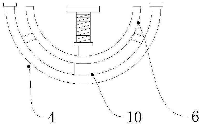
[0026] Example: such as figure 1 As shown, the present invention is an anti-collision structure for a new energy vehicle charging pile, including a base 1, a charging pile body 2, the top of the base 1 and the bottom of the charging pile body 2 are fixed to each other, and the surroundings of the charging pile body 2 are arranged There is a mounting plate 3, the front middle part of the mounting plate 3 is fixedly connected with a horizontal plate 5, the middle part of the horizontal plate 5 is longitudinally provided with a plurality of compression springs 9, the middle part of the horizontal plate 5 is horizontally provided with two card slots 8, and a plurality of compression springs One end of 9 is fixedly connected with a butt guard 6, and one end of the butt guard 6 is fixedly provided with a connector 10, and one end of the connector 10 is fixedly connected with an arc-shaped baffle 4, and two ends of the arc-shaped baffle 4 are provided with blocks 7. The two clamping ...


PUM


Abstract

The anti-collision structure for the new energy automobile charging pile comprises a base and a charging pile body, the top of the base and the bottom of the charging pile body are mutually fixed, mounting plates are arranged on the periphery of the charging pile body, a transverse plate is fixedly connected to the middle of the front face of each mounting plate, and a plurality of compression springs are longitudinally arranged in the middle of each transverse plate; two clamping grooves are transversely formed in the middle of the transverse plate, one ends of the multiple compression springs are fixedly connected with a butt joint protection plate, one end of the butt joint protection plate is fixedly provided with a connecting piece, one end of the connecting piece is fixedly connected with an arc-shaped baffle, clamping blocks are arranged at the two ends of the arc-shaped baffle, and the two clamping blocks and the clamping grooves are mutually inserted. According to the anti-collision structure for the new energy automobile charging pile, the anti-collision structures of different specifications are arranged on the periphery of the base and the periphery of the charging pile body, the anti-collision structure and the charging pile body are combined, the anti-collision effect can be effectively enhanced, and the phenomenon that due to the fact that an automobile collides with the charging pile, the charging pile inclines, and later charging is affected is avoided.

Description

technical field [0001] The invention relates to the technical field of charging piles, in particular to an anti-collision structure for charging piles of new energy vehicles. Background technique [0002] The function of the charging pile is similar to the refueling machine in the gas station. It can be fixed on the ground or wall, and installed in the parking lot or charging station of public buildings and residential areas. It can charge various types of electric vehicles according to different voltage levels. The input end of the charging pile is directly connected to the AC grid, and the output end is equipped with a charging plug for charging the electric vehicle. Charging piles generally provide two charging methods: conventional charging and fast charging. People can use a specific charging card to swipe the card on the human-computer interaction interface provided by the charging pile to perform corresponding charging methods, charging time, and cost data printing. ...

Claims


Application Information

Patent Timeline
Patent Type & Authority Applications(China)
IPC IPC(8): B60L53/31
CPCB60L53/31Y02T10/70Y02T10/7072Y02T90/12
Inventor 胡晓燕胡宇轩
Owner 南京宁绿江洲环保科技有限公司
Why Eureka
Try Eureka