Walking beam counterweight type pumping unit

A pumping unit and counterweight technology, which is applied in the direction of liquid variable capacity machinery, mechanical equipment, machine/engine, etc., can solve the problems of electrical equipment impact, energy waste, and adaptive adjustment

Pending Publication Date: 2022-05-10
肖云东
View PDF0 Cites 0 Cited by
  • Summary
  • Abstract
  • Description
  • Claims
  • Application Information

AI Technical Summary

Problems solved by technology

[0003] When the common beam counterweight pumping unit is in use, the counterweight structure helps the motor output power during the upstroke of the pumping unit, lifts the sucker rod, absorbs the potential energy of the sucker rod during the downstroke, increases its own potential energy, and realizes energy recovery. For recovery, the counterweight is usually set at the end of the beam away from the donkey’s head, and the position of the counterweight is adjusted with the set screw according to the potential energy generated by the stroke height, but the output of the counterweight will exceed the pumping force at the initial stroke stage. The load required by the oil rod will drive the motor to "reverse power generation". The potential energy generated by the counterweight according to the stroke height is adjusted by the screw to fix the position, and it cannot be adjusted adaptively according to the stroke up or down, which leads to the pumping unit every time The phenomenon of "reverse power generation" occurring twice in one stroke process not only wastes a part of energy, but also causes impact on electrical equipment and damages electrical equipment, which cannot meet the working requirements of the beam pumping unit with counterweight. beam pumping unit with counterweight

Method used


Image

  • Walking beam counterweight type pumping unit
  • Walking beam counterweight type pumping unit
  • Walking beam counterweight type pumping unit

Examples


Embodiment Construction

[0024] The following will clearly and completely describe the technical solutions in the embodiments of the present invention with reference to the accompanying drawings in the embodiments of the present invention. Obviously, the described embodiments are only some, not all, embodiments of the present invention. Based on the embodiments of the present invention, all other embodiments obtained by persons of ordinary skill in the art without making creative efforts belong to the protection scope of the present invention.

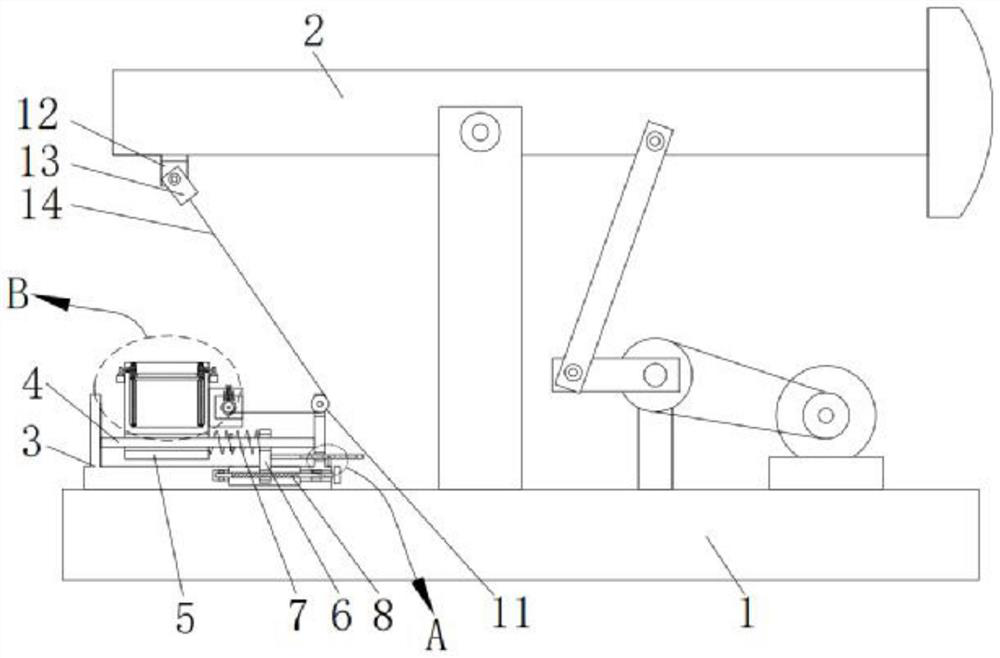
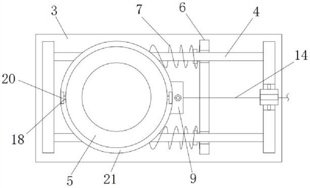
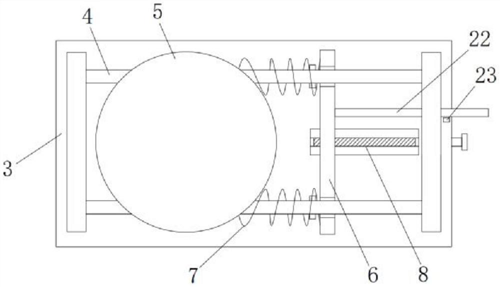
[0025] The present invention provides a technical solution, a beam-counterweight pumping unit, comprising a bottom plate 1, a support beam 2, a mounting shell 3, a mounting rod 4, a bearing shell 5, an adjusting plate 6, a compression spring 7, a first wire Rod 8, connecting shell 9, winding wheel 10, auxiliary wheel 11, electric slider 12, connecting block 13, steel wire rope 14, second screw mandrel 15, lifting plate 16, electric turntable 17, worm screw 18, ...


PUM


Abstract

The invention relates to the technical field of oil field oil pumping equipment, and discloses a walking beam balance weight type oil pumping unit which is characterized in that a supporting beam is movably mounted on a middle support of the upper surface of a bottom plate through a bearing, a mounting shell is welded to the left side of the upper surface of the bottom plate, and two mounting rods are symmetrically welded to the lower portion of an inner cavity of the mounting shell; and the same bearing shell is arranged on the outer walls of the two mounting rods in a sliding manner. When the walking beam counterweight type pumping unit is used, the first lead screw is arranged to drive the adjusting plate to move, the position of the electric sliding block is adjusted, the pumping unit can be applied to different stroke heights for counterweight under the action of the steel wire rope, and the distance between the two ends of the compression spring is adjusted according to the elastic coefficient of the compression spring; the position of the balancing weight can be changed in a self-adaptive mode under the action of elastic force of the compression spring, and therefore the problems that energy is wasted in the stroke process of the pumping unit, and meanwhile electrical equipment is impacted and damaged are solved.

Description

technical field [0001] The invention relates to the technical field of oil field pumping equipment, in particular to a beam-counterweight type pumping unit. Background technique [0002] The beam pumping unit is widely used in oil production equipment in oil fields due to its simple structure and durable skin. In order to reduce the power of the driving motor, the beam pumping unit will design a counterweight structure. The motor drives the crank through the belt and reducer to make a uniform circular motion, and the crank drives the beam of the four-bar linkage mechanism through the connecting rod. The fulcrum swings up and down, drives the donkey head suspension point at the front end of the beam (the suspension point is connected to the sucker rod), drives the plunger of the oil pump to reciprocate linearly up and down, and realizes mechanical oil recovery. [0003] When the common beam counterweight pumping unit is in use, the counterweight structure helps the motor out...

Claims


Application Information

Patent Timeline
IPC IPC(8): E21B43/00F04B47/14
CPCE21B43/121F04B47/14
Inventor 肖云东杨义
Owner 肖云东
Why Eureka
Try Eureka