Hydraulic source and hydraulic energy recycling system for non-road mobile machine

A mobile machine and hydraulic energy technology, which is applied in fluid pressure actuation system components, fluid pressure actuation system testing, mechanical equipment, etc., can solve problems such as hydraulic power loss, achieve effective recovery, and avoid energy loss.

Pending Publication Date: 2022-05-10
HEFEI SHINNY INSTR CONTROL TECH +1
View PDF0 Cites 0 Cited by
  • Summary
  • Abstract
  • Description
  • Claims
  • Application Information

AI Technical Summary

Problems solved by technology

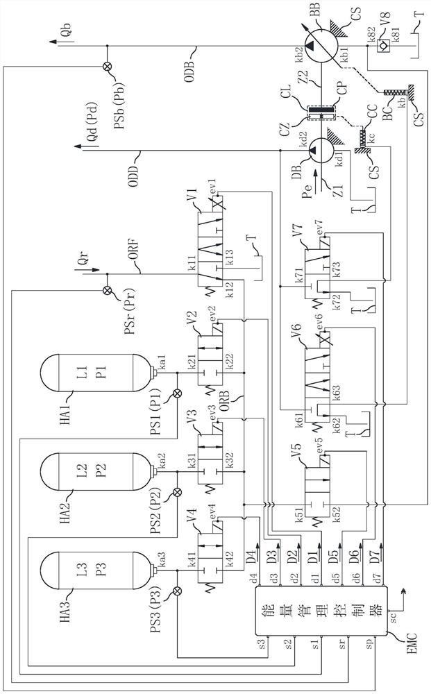
At present, the commonly used scheme in the design of hydraulic sources of non-road mobile machines is to configure hydraulic pumps to meet the maximum load conditions of the hydraulic actuators that consume the most hydraulic power. The valve components control the hydraulic supply parameters of the hydraulic source to the hydraulic actuators by means of shunting and throttling to complete the corresponding engineering operations. The advantage of this scheme is that it can meet the hydraulic drive power requirements of all hydraulic actuators. The operation can realize fast response and relatively accurate control, but because the diversion process of the valve components usually allows the pressure oil from the diversion to flow back directly to the hydraulic oil tank, resulting in hydraulic power loss, and at the same time, the valve components themselves The hydraulic pressure difference between the front of the valve and the back of the valve also causes a loss of hydraulic power. In addition, the size of the hydraulic power is positively related to the pressure and flow of the oil, and hydraulic actuators generally use linear or rotary hydraulic cylinders as actuators. When working, the operation is completed by supplying pressure oil to the working chamber of the hydraulic cylinder or discharging oil from the working chamber of the hydraulic cylinder. Usually, the oil discharged from the hydraulic cylinder is directly returned to the hydraulic oil tank, because the discharged oil has a certain oil Pressure, so also formed a certain hydraulic power loss

Method used


Image

  • Hydraulic source and hydraulic energy recycling system for non-road mobile machine
  • Hydraulic source and hydraulic energy recycling system for non-road mobile machine
  • Hydraulic source and hydraulic energy recycling system for non-road mobile machine

Examples


Embodiment Construction

[0049] Embodiments of the present invention are described below through specific examples, and those skilled in the art can easily understand other advantages and effects of the present invention from the content disclosed in this specification. The present invention can also be implemented or applied through other different specific implementation modes, and various modifications or changes can be made to the details in this specification based on different viewpoints and applications without departing from the spirit of the present invention. It should be noted that, in the case of no conflict, the following embodiments and features in the embodiments can be combined with each other.

[0050] It should be noted that the diagrams provided in the following embodiments are only schematically illustrating the basic ideas of the present invention, and only the components related to the present invention are shown in the diagrams rather than the number, shape and number of componen...


PUM


Abstract

The invention belongs to the field of non-road mobile machines, and particularly relates to a hydraulic source and hydraulic energy recycling system for a non-road mobile machine, which comprises a first hydraulic pump, a second hydraulic pump, a third hydraulic pump and a fourth hydraulic pump, the first oil supply channel is connected between an oil outlet of the first hydraulic pump and an oil inlet of the hydraulic actuating module; the oil return channel is connected to an oil return opening of the hydraulic actuating module; an energy storage module; the energy storage module is connected to the oil return channel and comprises an energy accumulator and an energy storage control valve; the pressure compensation oil channel is connected between the energy storage module and an oil inlet of the first hydraulic pump, and a pressure compensation control valve used for controlling the pressure compensation oil channel to be connected or disconnected is arranged on the pressure compensation oil channel. The hydraulic power loss of the non-road mobile machine is reduced, the power consumption is reduced, and the energy utilization rate is improved.

Description

technical field [0001] The invention belongs to the field of non-road mobile machines, and in particular relates to a hydraulic source and hydraulic energy recovery and reuse system for non-road mobile machines. Background technique [0002] There are many types of mobile machines, and the common feature is that the machine works in a mobile way or the machine needs to move during the operation; according to the usage scenarios, mobile machines can be roughly divided into two categories: road and non-road. Road mobile machines are mainly vehicles that run on artificial roads and are used for passenger and cargo transportation. Non-road mobile machines mainly include various mobile construction machinery such as forklifts, excavators, loaders, and cranes, as well as self-propelled agricultural equipment, Military vehicles, etc. During the working process, in addition to moving by itself, non-road mobile machines also need to complete certain specific engineering operations t...

Claims


Application Information

Patent Timeline
Patent Type & Authority Applications(China)
IPC IPC(8): F15B11/17F15B1/02F15B13/02F15B21/08F15B19/00
CPCF15B11/17F15B1/02F15B13/027F15B13/02F15B21/08F15B19/00F15B2211/20546F15B2211/30505
Inventor 孙冬汪韶杰魏玉龙盛楠夏光孙保群纵华宇于星海
Owner HEFEI SHINNY INSTR CONTROL TECH
Why Eureka
Try Eureka