In-bottle pressure reduction and self-locking integrated electromagnetic valve

An integrated, electromagnetic valve technology, applied in the field of electromagnetic valves, can solve the problems of high assembly cost, high energy consumption, and many gas accessories, and achieve the effect of multiple functions and low energy consumption

Pending Publication Date: 2022-05-10
NINGBO ANLITE MACHINERY CO LTD
View PDF0 Cites 1 Cited by
  • Summary
  • Abstract
  • Description
  • Claims
  • Application Information

AI Technical Summary

Problems solved by technology

[0004] 1. For a normally open solenoid valve, if you want to close the solenoid valve, you need the seal to keep blocking the second exhaust port, that is, you need to keep the coil continuously energized; similarly, for the normally closed solenoid valve, if you want to open the solenoid valve The seal needs to be kept out of the valve port, that is, the coil needs to be kept in a continuous energized state, but the coil is easily damaged if the coil is kept in a continuous energized state, the service life is greatly reduced, and the energy consumption is also high;
[0005] 2. The existing solenoid valves are normally open or normally closed. When a normally open type is required, a normally open solenoid valve must be selected. When a normally closed type is required, a normally closed solenoid valve must be selected. Switching is required;
[0006] 3. The existing solenoid valve at the bottle mouth is generally arranged outside the bottle body, and the existing solenoid valve at the bottle mouth needs to connect the air pipe and the corresponding connecting joint to the bottle mouth of the bottle body, so more gas fittings are required and the assembly cost is higher. high

Method used


Image

  • In-bottle pressure reduction and self-locking integrated electromagnetic valve
  • In-bottle pressure reduction and self-locking integrated electromagnetic valve
  • In-bottle pressure reduction and self-locking integrated electromagnetic valve

Examples


Embodiment Construction

[0033] The present invention will be further described below in conjunction with the accompanying drawings.

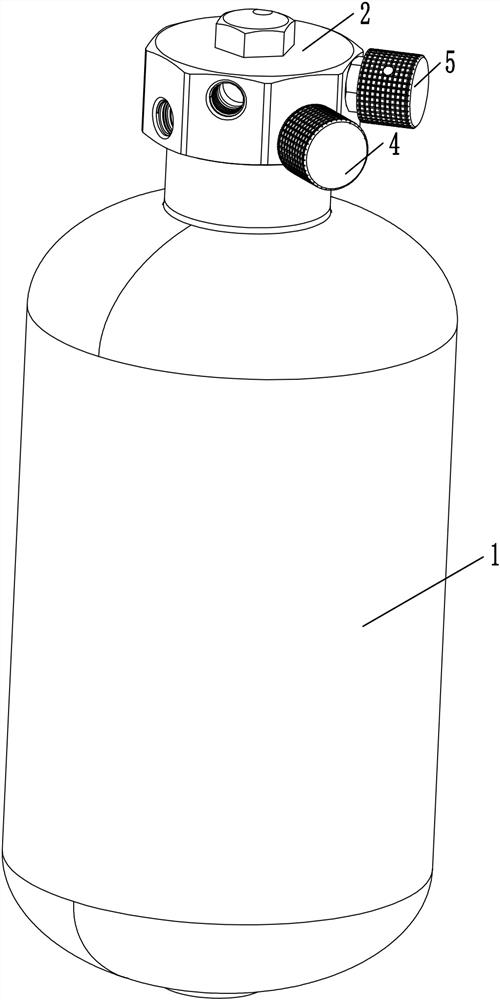
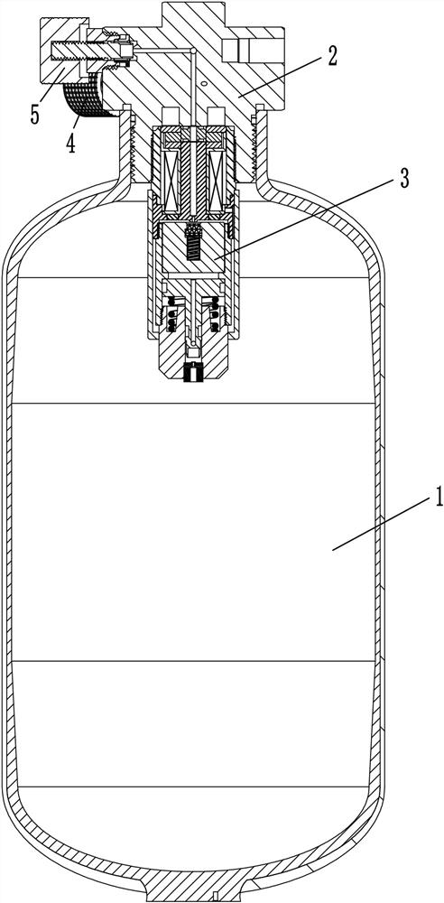
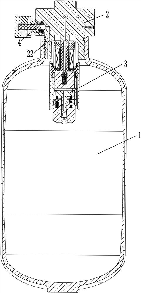
[0034] like Figure 1-8 As shown, a bottle-in-bottle decompression self-locking integrated solenoid valve includes a bottle body 1, a valve cover 2 and a solenoid valve assembly 3. The bottle body 1 is provided with an inner cavity for storing gas, and the valve cover 2 is sealed. In the bottle mouth of the bottle body 1, in the present invention, the valve cover 2 is threadedly connected to the bottle mouth of the bottle body 1, and the valve cover 2 is provided with at least one sealing ring, such as image 3 and Figure 5As shown, the valve cover 2 is provided with an inflation port 21 and an air intake channel 22 connecting the inflation port 21 and the inner cavity of the bottle body 1, and the gas to be stored enters the inner cavity of the bottle body 1 through the inflation port 21 for storage. The air channel 22 is provided on the valve cover 2 at a position...


PUM


Abstract

The in-bottle pressure reduction and self-locking integrated electromagnetic valve comprises a bottle body, a valve cover and an electromagnetic valve assembly, the valve cover is arranged at a bottle opening of the bottle body, and the valve cover is provided with an inflation inlet and an air inlet channel; the electromagnetic valve assembly comprises a magnetic conductive sleeve, a static iron core, a movable iron core, a framework and a strong magnet, the magnetic conductive sleeve is connected to the lower portion of the valve deck, the framework is arranged in the magnetic conductive sleeve, the static iron core is fixedly arranged in the framework, a coil is wound on the periphery of the framework, a magnetic isolation sleeve is arranged on the lower portion of the magnetic conductive sleeve, the movable iron core is arranged in the magnetic isolation sleeve, and the movable iron core makes contact with the static iron core when attracted upwards. An elastic piece I is arranged between the static iron core and the movable iron core, the strong magnet is installed on the framework, the movable iron core is provided with a first exhaust passage, the lower portion of the magnetism isolating sleeve is provided with a valve nozzle, the static iron core is provided with a second exhaust passage, the position, corresponding to the second exhaust passage, of the movable iron core is provided with a sealing structure, and the valve deck is provided with an exhaust port and a third exhaust passage communicated with the exhaust port and the second exhaust passage. Through the arrangement, free switching between normally-closed state and normally-open state of the electromagnetic valve can be realized.

Description

technical field [0001] The invention relates to the technical field of electromagnetic valves, in particular to an integrated electromagnetic valve for decompression and self-locking in a bottle. Background technique [0002] The decompression and self-locking integrated solenoid valve is set on the sealing port of the bottle body. The opening and closing of the bottle mouth can be controlled through the solenoid valve. The existing solenoid valve is normally open or normally closed. The normally open solenoid valve includes a pipe body , the static iron core fixed in the tube body, the movable iron core set in the tube body, the elastic reset piece between the static iron core and the moving iron core, and the coil wound around the outer periphery of the tube, among which the moving valve The core is provided with a first exhaust channel connected with the inside of the bottle body, the middle part of the static iron core is provided with a second exhaust channel connected ...

Claims


Application Information

Patent Timeline
Patent Type & Authority Applications(China)
IPC IPC(8): F16K31/08F16K17/00F16K31/363F16K1/00F16K27/08F16K37/00F16K11/22F17C13/02F17C13/04
CPCF16K31/0655F16K31/0675F16K31/082F16K17/00F16K31/363F16K1/00F16K27/08F16K37/00F16K11/22F17C13/025F17C13/04F17C2250/043
Inventor 陈志法唐猛
Owner NINGBO ANLITE MACHINERY CO LTD
Why Eureka
Try Eureka