Ceiling lamp with smoke alarm function

A smoke alarm and ceiling lamp technology, which is applied to alarms, fire alarms that rely on smoke/gas effects, lampshades, etc., can solve the problems of inconvenient smoke alarms, inconvenient wiring, inconvenient replacement, etc., and reduce the cost of replacing lamp rings Difficulty, ease of cleaning, and better safety

Inactive Publication Date: 2022-05-10
中山市温宇光电科技有限公司
View PDF0 Cites 0 Cited by
  • Summary
  • Abstract
  • Description
  • Claims
  • Application Information

AI Technical Summary

Problems solved by technology

[0006] The purpose of the present invention is to provide a ceiling lamp with a smoke alarm function to solve the problems of inconvenient smoke alarm, inconvenient wiring and inconvenient replacement of the lamp ring proposed in the above background technology

Method used


Image

  • Ceiling lamp with smoke alarm function
  • Ceiling lamp with smoke alarm function
  • Ceiling lamp with smoke alarm function

Examples


Embodiment 1

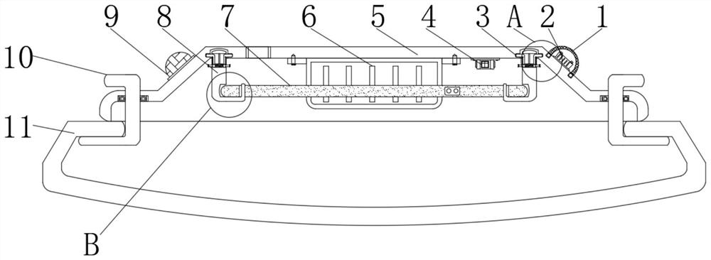
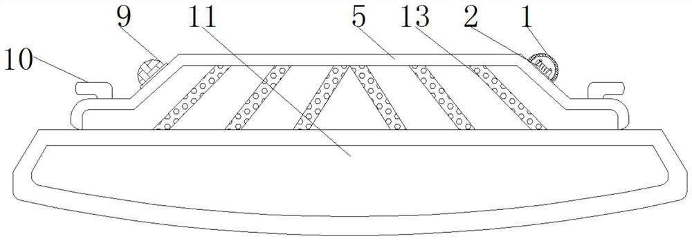
[0062] Example 1: See Figure 1-5 , a ceiling lamp with a smoke alarm function, including a ceiling cover 5 and a lampshade 11, and also includes an installation structure 3 for easy replacement, a connection structure 12 for connecting wires and a smoke alarm mechanism for improving use safety;

[0063] A rectifier bridge 6 is installed in the middle of the bottom end of the ceiling cover 5, and the connection structure 12 is installed inside the ceiling cover 5 on both sides of the rectifier bridge 6 through wires;

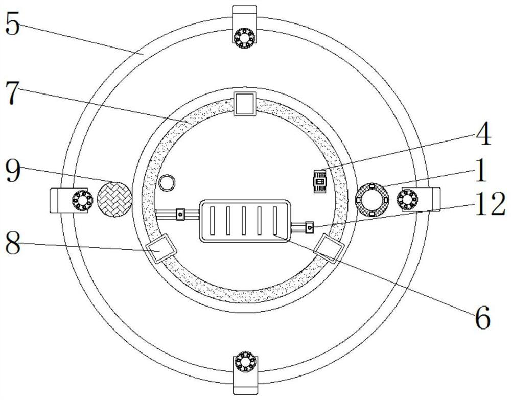
[0064] A single-chip microcomputer 4 is installed on the inner top of the ceiling cover 5 on one side of the rectifier bridge 6. The model of the single-chip microcomputer 4 can be STM32F103RCT6, and a support frame 8 is evenly and vertically arranged around the inner top of the ceiling cover 5, and a suction frame 8 at the bottom of the support frame 8. The inside of the top cover 5 is provided with a light ring 7, and the installation structure 3 is arranged o...

Embodiment 2

[0072] Embodiment 2: The mounting structure 3 includes a mounting groove 301, a mounting block 302, an L-shaped mounting rod 303, a sliding rod 304, a mounting spring 305, a fixing groove 306 and a mounting hole 307, and the mounting groove 301 is evenly opened on the inner wall of the ceiling cover 5. The top, and the top of the ceiling cover 5 inner wall at the lower end of the installation groove 301 both sides are provided with installation holes 307, and the top of the support frame 8 is equipped with an installation block 302 that matches the installation groove 301, and the upper ends of the installation block 302 are all horizontal A fixing groove 306 is provided, and an installation spring 305 is installed at the middle position inside the fixing groove 306, and the inside of the fixing groove 306 on both sides of the installation spring 305 is slidably connected with a slide bar 304 extending to the outside of the support frame 8, and the slide bar 304 L-shaped mounti...

Embodiment 3

[0075] Embodiment 3: the connection structure 12 comprises a return spring 1201, a movable conductive block 1202, a fixed conductive groove 1203, an insulating plate 1204, an insulating box 1205 and an insulating rod 1206, and the insulating box 1205 is installed on both sides of the rectifier bridge 6 by wires, and Both sides of the inner bottom of the insulating box 1205 are equipped with fixed conductive grooves 1203, and both sides of the inner top of the insulating box 1205 are equipped with return springs 1201, and the insulating box 1205 at the bottom of the return spring 1201 is slidingly connected with an insulating plate 1204. Movable conductive blocks 1202 are installed on both sides of the bottom of the plate 1204, and an insulating rod 1206 extending to the outside of the insulating box 1205 is installed vertically in the middle of the top of the insulating plate 1204;

[0076] Specifically, such as figure 2 and Figure 5As shown, by pulling the insulating rod 1...


PUM


Abstract

The ceiling lamp with the smoke alarm function comprises a ceiling cover and a lampshade and further comprises a mounting structure convenient to replace, a connecting structure convenient to connect with a wire and a smoke alarm mechanism capable of improving the use safety, and a rectifier bridge is mounted in the middle of one end of the bottom end of the interior of the ceiling cover; the connecting structures are installed in the ceiling cover on the two sides of the rectifier bridge through wires, a single-chip microcomputer is installed at the top end in the ceiling cover on one side of the rectifier bridge, supporting frames are evenly and vertically arranged on the periphery of the top end in the ceiling cover, a lamp ring is arranged in the ceiling cover at the bottom ends of the supporting frames, and a lampshade is arranged at the bottom end of the ceiling cover. And the smoke alarm mechanism is arranged at the upper end of one side of the ceiling cover. The smoke sensor and the buzzer are arranged, the smoke sensor is used for detecting the indoor smoke concentration in real time, and when the indoor smoke concentration exceeds the preset value, the buzzer gives an alarm to remind a user to check in time, and fire hazards are avoided.

Description

technical field [0001] The invention relates to the technical field of ceiling lamps, in particular to a ceiling lamp with a smoke alarm function. Background technique [0002] With the development of society and the improvement of the living standards of Chinese residents, the requirements for the living environment are getting higher and higher, and the ceiling lamp is loved by consumers because of its excellent performance and aesthetics, and the most popular in the market The most popular is led ceiling lamps, which are often used in various places such as homes, offices, entertainment venues, etc., but there are still many problems or defects in existing ceiling lamps: [0003] First, the traditional ceiling lamp does not have a smoke alarm structure when it is used. When a fire occurs accidentally, it cannot be alarmed in time. [0004] Second, the traditional ceiling lamp does not have a convenient wiring structure when used. When connecting wires, it is usually nece...

Claims


Application Information

Patent Timeline
Patent Type & Authority Applications(China)
IPC IPC(8): F21S8/04F21V33/00A01M29/34F21V17/16F21V23/00F21V17/10F21V15/01F21V3/00F21V23/02H05B47/10G08B17/10G08B21/24
CPCF21S8/04F21V33/0076A01M29/34F21V17/162F21V23/001F21V17/10F21V15/01F21V3/00F21V23/02F21V23/003H05B47/10G08B17/10G08B21/24Y02B20/40
Inventor 玉梅花
Owner 中山市温宇光电科技有限公司
Why Eureka
Try Eureka