Intelligent wearable device and preparation process thereof
A wearable device and manufacturing process technology, which is applied in the field of intelligent wearable devices and its preparation process, can solve problems such as affecting battery life, poor recognition effect, and signal loss, so as to improve diversified design space, ensure integrated structure, The effect of reducing the amount of signal loss
- Summary
- Abstract
- Description
- Claims
- Application Information
AI Technical Summary
Problems solved by technology
Method used
Image
Examples
Embodiment 1
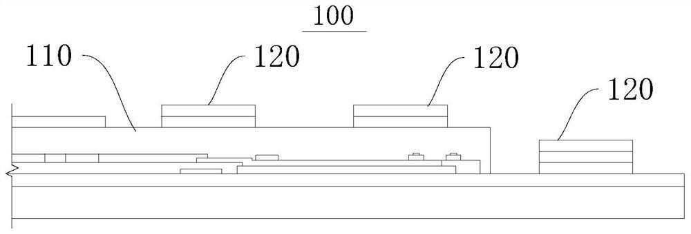
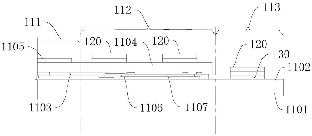
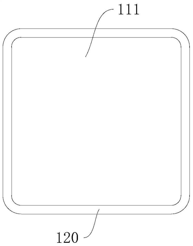
[0061] Please refer to figure 1 , this embodiment provides an integrated display module 100 . The integrated display module 100 includes: a display module 110 and an NFC module 120 . Wherein, the NFC module 120 is located on the display side of the display module 110 .
[0062] Wherein, "display side" refers to the side of the display module 110 away from its back, opposite to the side where its back is located, and is only used to refer to the orientation, not to refer to the area where it actually performs the display function.
[0063] The NFC module 120 is directly integrated into the display module 110, getting rid of the dependence on other components, and also releasing the constraints of the NFC module 120 on other components, so that the NFC module 120 and other components can be designed more flexibly, and It helps to improve the diversified design space of corresponding products. In addition, the NFC module 120 is located on the display side of the display module...
Embodiment 2
[0086] Please refer to Figure 10 , this embodiment provides an integrated display module 200 . Compared with the integrated display module 100 in Embodiment 1, the difference is that the display module 210 of the integrated display module 200 is in the shape of a ring as a whole, which is a ring screen. Wherein, the central axis of the display module 210 is arranged parallel to the surface of its display area. The NFC module 220 extends in a ring shape along one edge of the display module 210 .
[0087] It can be understood that the NFC module 220 can also be arranged on both sides of the display module 210, such as Figure 11 shown.
[0088] In other embodiments of the present invention, the display module can also be a ring structure of other shapes, such as a rectangular ring shape, an elliptical ring shape, etc., and is not limited thereto.
Embodiment 3
[0090] Please refer to Figure 12 , this embodiment provides an integrated display module 300 . Compared with the integrated display module 100 in Embodiment 1, the difference is that the display module 310 of the integrated display module 300 is in the shape of a ring as a whole, which is a ring screen. Wherein, the central axis of the display module 310 is arranged perpendicular to the surface of its display area. The NFC module 320 is disposed on the outer edge of the display module 310 and extends in a ring shape along the outer edge of the display module 310 .
[0091] It can be understood that the NFC module 320 can also be arranged on the inner edge of the display module 310, such as Figure 13 shown; NFC module 320 can also be set on the outside edge and inside edge of display module 310, as Figure 14 shown.
[0092] In other embodiments of the present invention, the display module can also be a ring structure of other shapes, such as a rectangular ring shape, an ...
PUM
 Abstract
Description
Claims
Application Information
 - R&D
- Intellectual Property
- Life Sciences
- Materials
- Tech Scout
- Unparalleled Data Quality
- Higher Quality Content
- 60% Fewer Hallucinations
Browse by: Latest US Patents, China's latest patents, Technical Efficacy Thesaurus, Application Domain, Technology Topic, Popular Technical Reports.
© 2025 PatSnap. All rights reserved.Legal|Privacy policy|Modern Slavery Act Transparency Statement|Sitemap|About US| Contact US: help@patsnap.com


