End insulating plate, battery device and assembling method of battery device

A battery device and terminal insulation technology, which is applied to battery components, battery and its environment isolation, circuits, etc., can solve the problems that affect the assembly yield of battery devices, the installation of terminal insulation boards is not in place, and unfavorable industrial production. Good bonding effect, guaranteed adhesive effect, and improved assembly yield

Pending Publication Date: 2022-05-10
CALB CO LTD
View PDF0 Cites 0 Cited by
  • Summary
  • Abstract
  • Description
  • Claims
  • Application Information

AI Technical Summary

Problems solved by technology

[0002] In the assembly process of the battery device, the two ends of each battery pack are generally bonded to the terminal insulating plate, and then put into the box, and before the battery pack with both ends bonded to the terminal insulating plate is put into the box, Glue will be applied to the end insulation plates and / or beams to allow the battery pack to be bonded to the beams when placed in the box; however, when the battery pack is placed in the box, the glue applied in advance will Scratched to other positions, resulting in low bonding strength after coating and curing and / or improper installation of terminal insulation boards, etc., which directly affects the assembly yield of the battery device and is not conducive to industrial production

Method used


Image

  • End insulating plate, battery device and assembling method of battery device
  • End insulating plate, battery device and assembling method of battery device
  • End insulating plate, battery device and assembling method of battery device

Examples


Embodiment Construction

[0031] The following will clearly and completely describe the technical solutions in the exemplary embodiments of the present disclosure with reference to the accompanying drawings in the exemplary embodiments of the present disclosure. The exemplary embodiments described herein are for illustrative purposes only, and are not intended to limit the protection scope of the present disclosure, so it should be understood that various modifications can be made to the exemplary embodiments without departing from the protection scope of the present disclosure. modifications and changes.

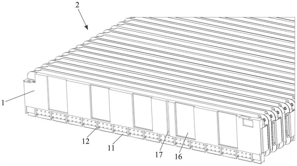
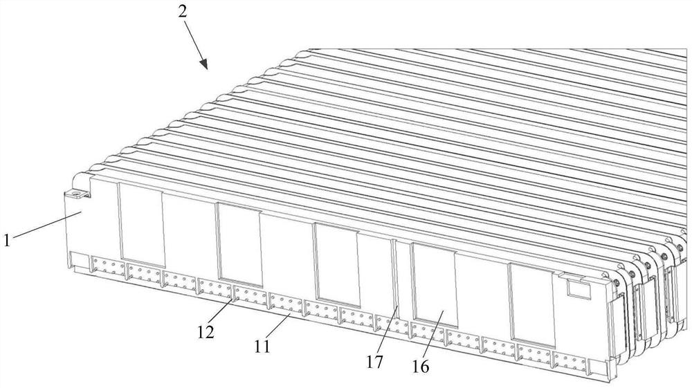
[0032] In the related technology, the box of the battery pack is surrounded by beams to form a cavity, and the battery pack is directly inserted into the cavity surrounded by the beams; in order to increase the insulation performance, avoid damage to the battery, and reduce friction, the battery pack is generally placed End insulating plates are provided at both ends. With such an arrangement, if t...


PUM

PropertyMeasurementUnit
lengthaaaaaaaaaa

Abstract

The invention relates to the technical field of batteries, and discloses an end insulating plate, a battery device and an assembling method of the battery device. The end insulating plate is used for being arranged in the battery device so as to insulate a battery pack from other parts, and a rubber blocking plate is arranged at the bottom of the end insulating plate, can be bent and at least has a first state and a second state; in the first state and the second state, the rubber blocking plate is bent towards one side of the first large surface of the end insulating plate, and the first large surface is a large surface of one side, deviating from the battery pack, of the end insulating plate; in the first state, the rubber blocking plate forms a first dip angle relative to the first large surface of the end insulating plate, in the second state, the rubber blocking plate forms a second dip angle relative to the first large surface of the end insulating plate, and the first dip angle is larger than the second dip angle. The glue blocking plate is configured to push glue at the bottom of the end insulation plate in the direction away from the bottom of the end insulation plate when the first inclination angle is changed into the second inclination angle. According to the end insulating plate provided by the invention, the assembly yield of the battery device can be improved, and industrial production is facilitated.

Description

technical field [0001] The invention relates to the technical field of batteries, in particular to an end insulating plate, a battery device and an assembly method of the battery device. Background technique [0002] In the assembly process of the battery device, the two ends of each battery pack are generally bonded to the terminal insulating plate, and then put into the box, and before the battery pack with both ends bonded to the terminal insulating plate is put into the box, Glue will be applied to the end insulation plates and / or beams to allow the battery pack to be bonded to the beams when placed in the box; however, when the battery pack is placed in the box, the glue applied in advance will Scratched to other positions, resulting in low bonding strength after coating and curing and / or improper installation of terminal insulation boards, etc., which directly affects the assembly yield of the battery device and is not conducive to industrial production. Contents of ...

Claims


Application Information

Patent Timeline
Patent Type & Authority Applications(China)
IPC IPC(8): H01M50/24H01M50/244H01M50/289
CPCH01M50/289H01M50/244H01M50/24Y02E60/10H01M50/209H01M50/204H01M50/593H01M2220/20H01M50/291
Inventor 赵冬
Owner CALB CO LTD
Why Eureka
Try Eureka