
DC power supply device and servo DC power supply system

A technology of direct current power supply and direct current, applied in the direction of direct current network circuit devices, circuit devices, output power conversion devices, etc., can solve problems such as interference voltage, unable to speed up switching speed, oscillation, etc., and achieve the effect of suppressing voltage oscillation

Pending Publication Date: 2022-05-10
ORMON CORP
View PDF0 Cites 0 Cited by
  • Summary
  • Abstract
  • Description
  • Claims
  • Application Information

AI Technical Summary

Problems solved by technology

In such a system, there is a problem that in order to reduce the radiation noise from the long cable between the motor and the servo driver, the switching speed cannot be increased, and a large number of cables are required for the connection between the motor and the servo driver.
However, in a system employing this configuration, the LC circuit on the DC bus side may interfere with the motor control device side, causing the voltage of the DC bus to oscillate (for example, see Non-Patent Document 1).

Method used


Image

  • DC power supply device and servo DC power supply system
  • DC power supply device and servo DC power supply system
  • DC power supply device and servo DC power supply system

Examples


Embodiment Construction

[0022] Hereinafter, embodiments of the present invention will be described with reference to the drawings.

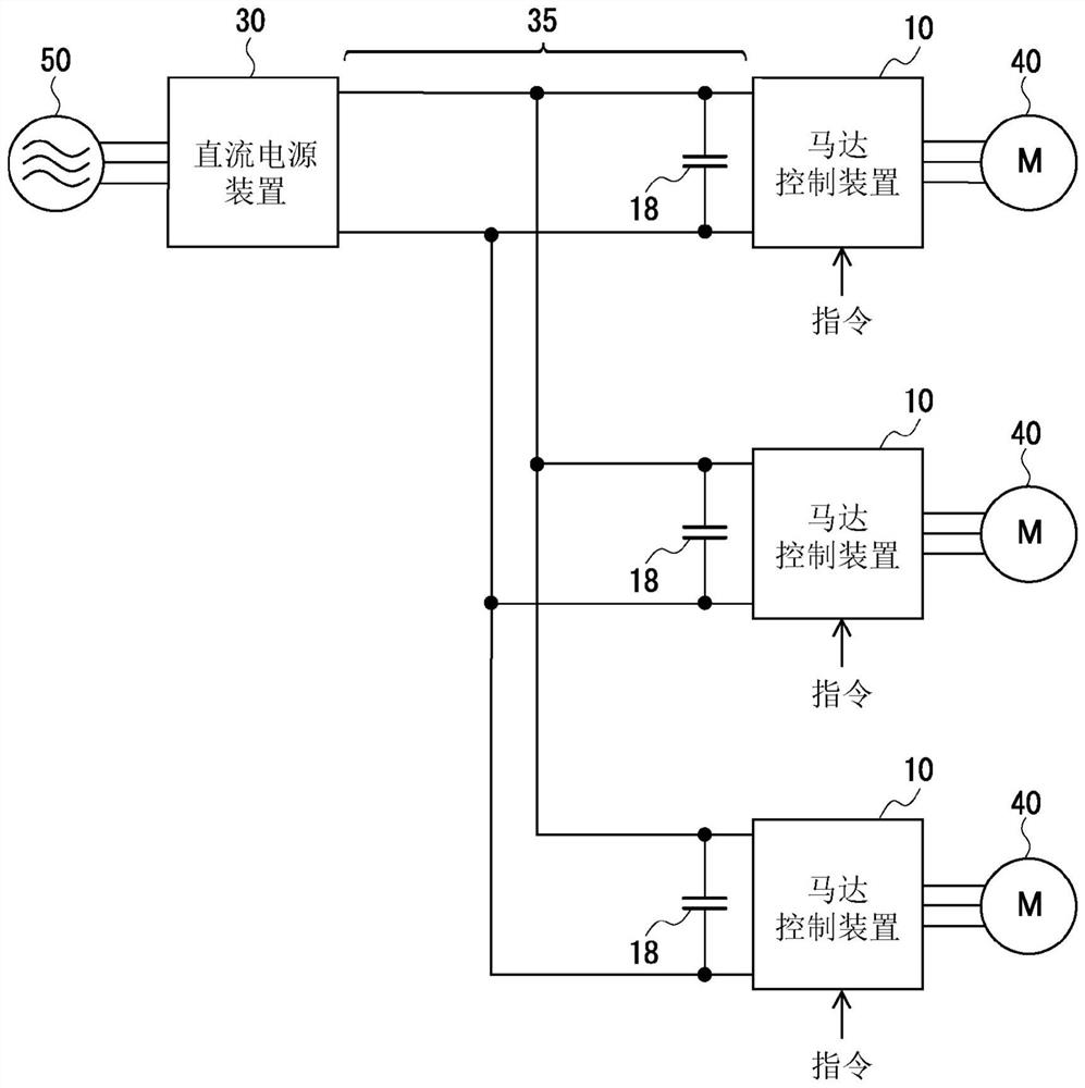
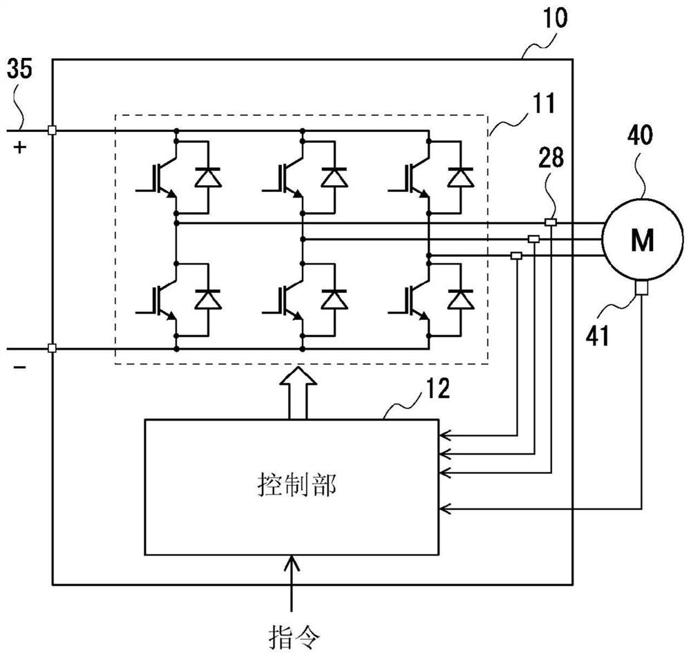
[0023] figure 1 Showing a schematic configuration of a servo DC power supply system according to an embodiment of the present invention, figure 2 A schematic configuration of the motor control device 10 included in the servo DC power supply system is shown.

[0024] Such as figure 1 As shown, the servo DC power supply system of the present embodiment is a system in which a DC power supply device 30 and a plurality of motor control devices 10 are connected via a power supply path 35 .

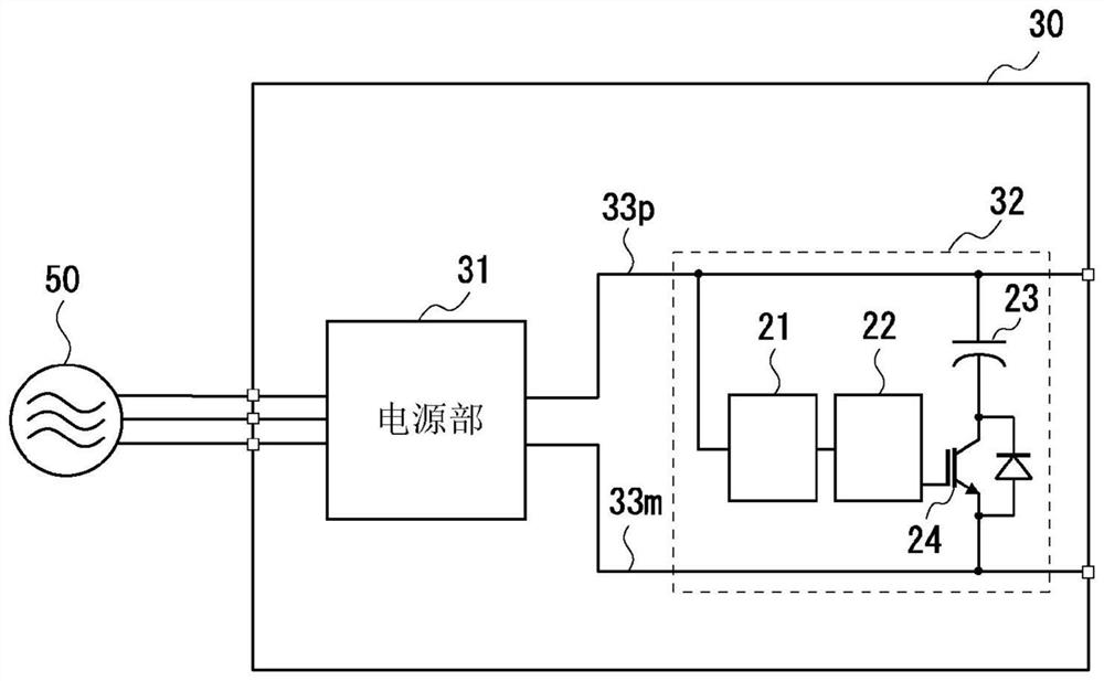
[0025] The DC power supply unit 30 is a power supply that outputs a predetermined DC voltage. The details of this DC power supply device 30 will be described later.

[0026] The motor control device 10 controls a servo motor 40 (hereinafter also simply referred to as the motor 40 ) in accordance with commands (position command, speed command, etc.) from a higher-level device such as ...


PUM


Abstract

The invention provides a DC power supply device capable of suppressing voltage oscillation of a power supply path to a motor control device. A DC power supply device is provided with: a power supply unit (AC / DC converter or the like) that outputs DC power; and a filter circuit that detects a voltage variation in the direct current output from the power supply unit, and adjusts the impedance of the circuit so as to suppress the voltage variation in the direct current on the basis of the detection result.

Description

technical field [0001] The invention relates to a DC power supply device and a servo DC power supply system. Background technique [0002] In a factory or the like, a system in which a plurality of motors are PWM-driven by a plurality of servo drivers arranged in separate places (a system composed of a robot and its control device, etc.) is used. In such a system, there is a problem that the switching speed cannot be increased in order to reduce radiation noise from the long cable between the motor and the servo driver, and a large number of cables are required for the connection between the motor and the servo driver. [0003] If a device (hereinafter, referred to as a motor control device) is arranged near each motor with the inverter removed from the servo driver, and power is supplied to each motor control device from a DC power supply device through a DC bus, it is possible to avoid the occurrence of above question. However, in a system employing this configuration, t...

Claims


Application Information

Patent Timeline
Patent Type & Authority Applications(China)
IPC IPC(8): H02M1/14H02J1/00
CPCH02M1/15H02M1/008H02M5/458H02J1/06H02M1/14H02M7/5387H02P5/74
Inventor 桐渊岳财津俊行芦田岳史土井昌志
Owner ORMON CORP
Learn More