Critical patient transfer chair for emergency department

A technology for critically ill patients, applied in the field of transport chairs for critically ill patients in the emergency department

Inactive Publication Date: 2022-05-13
KAIFENG CENT HOSPITAL
View PDF0 Cites 0 Cited by
  • Summary
  • Abstract
  • Description
  • Claims
  • Application Information

AI Technical Summary

Problems solved by technology

[0003] In view of the above situation, in order to overcome the defects of the prior art, the present invention provides a transport chair for critically ill patients in the emergency department. The present invention has a novel structure, ingenious concept, simple and convenient operation, and effectively solves the problem of injury caused by changing beds for patients. Added the automatic sealing function of the vomit dustbin, added the function of height adjustment, optimized the function of the adjustment of the hand support plate, and added the function of pressing the garbage bag on the edge of the garbage bin

Method used


Image

  • Critical patient transfer chair for emergency department
  • Critical patient transfer chair for emergency department
  • Critical patient transfer chair for emergency department

Examples


Embodiment 1

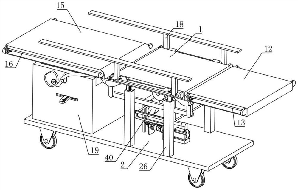
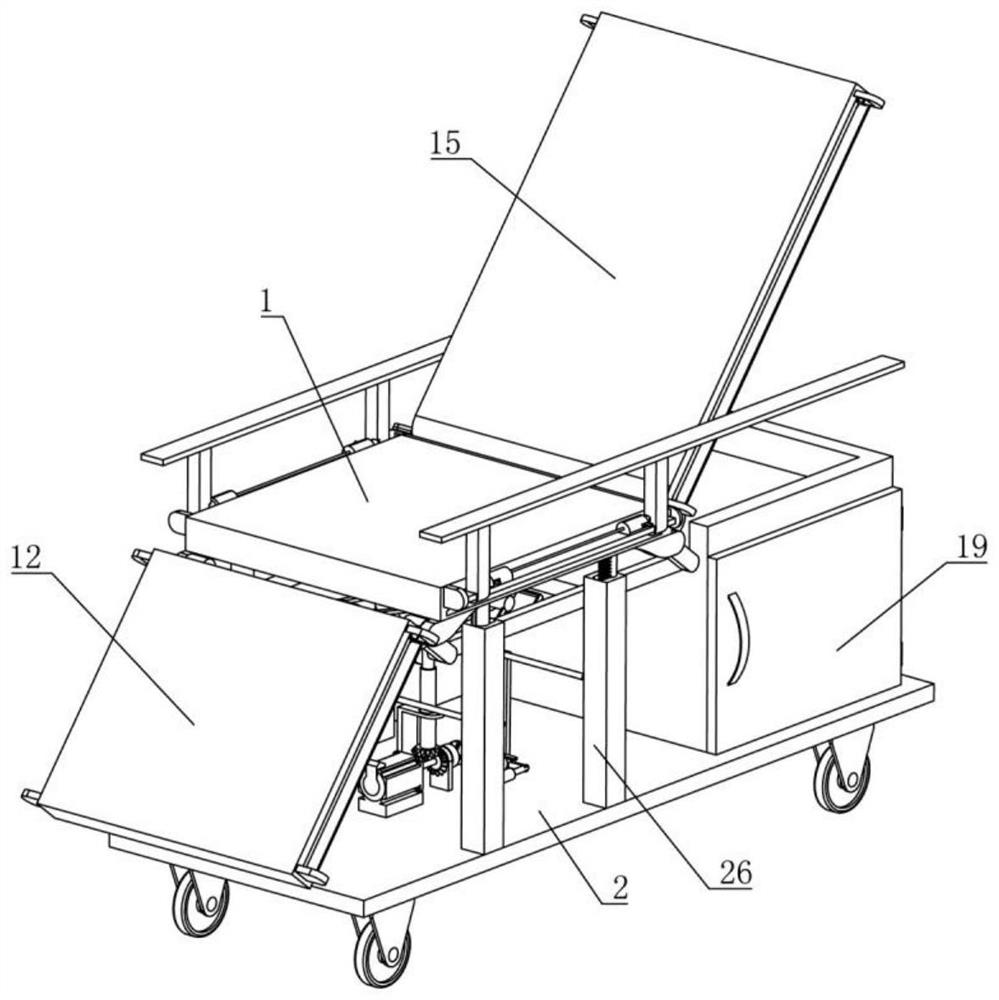
[0039] Embodiment one, by Figure 1-Figure 23 Given, the utility model includes a seat plate 1 and a support plate 2, the inside of the seat plate 1 is rotatably connected with a first rotating gear 3, the front and rear sides of the first rotating gear 3 are meshed with a tooth plate 4, the There are two first H plates 5 slidingly connected inside the seat plate 1, one end of each tooth plate 4 is fixedly connected with the corresponding first H plate 5, each of the first H plates 5 is close to the tooth plate 4 One side of the seat plate 1 is rotatably connected with a plurality of first connecting rods 6, and the inside of the seat plate 1 is provided with two first expansion plates 7, and the first expansion plates 7 slide inside the seat plate 1, and each first expansion plate 7 is It is rotatably connected with the corresponding first connecting rod 6, the lower end of the seat plate 1 is rotatably connected with a gear rod 8, and the outer side of the gear rod 8 is slid...

Embodiment 2

[0043] Embodiment two, on the basis of embodiment one, by figure 1 , figure 2 , Image 6 with Figure 9 Given, in order to achieve the purpose of expanding the leg plate 12, the first expansion mechanism 13 includes a second pulley 1301 that is rotatably connected to the seat plate 1, and the lower end of the leg plate 12 is rotatably connected to a first rotating rod 1302, a third belt 1303 is set between the first rotating rod 1302 and the second pulley 1301, the left side of the first rotating rod 1302 is meshed with a second rotating gear 1304, the front and rear of the second rotating gear 1304 A sliding tooth 1305 is meshed on each side, and two second H plates 1306 are slidably connected to the inside of the leg plate 12, and one end of each sliding tooth 1305 is fixedly connected with the corresponding second H plate 1306, each The side of the second H plate 1306 close to the sliding teeth 1305 is rotatably connected with a plurality of second connecting rods 1307,...

Embodiment 3

[0045] Embodiment three, on the basis of embodiment one, by figure 1 , figure 2 , Figure 7 with Figure 10 Given, in order to achieve the purpose of expanding the backboard 15, the second expansion mechanism 16 includes a third pulley 1601 that is rotatably connected to the seat board 1, and the lower end of the backboard 15 is rotatably connected to a second rotating rod 1602, a fourth belt 1603 is set between the second rotating rod 1602 and the third pulley 1601, the left side of the second rotating rod 1602 is meshed with a third rotating gear 1604, the front and rear of the third rotating gear 1604 Each side is engaged with a moving tooth 1605, and two third H plates 1606 are slidably connected to the inside of the back plate 15, and one end of each moving tooth 1605 is fixedly connected with the corresponding third H plate 1606, each The side of the third H plate 1606 close to the moving teeth 1605 is rotatably connected with a plurality of third connecting rods 160...


PUM


Abstract

A critical patient transfer chair for the emergency department effectively solves the problem that a patient is injured due to bed changing, comprises a seat plate and a supporting plate, and is characterized in that a first rotating gear is rotationally connected into the seat plate, and the front side and the rear side of the first rotating gear are each meshed with a toothed plate; two first H-shaped plates are slidably connected to the interior of the seat plate, one end of each toothed plate is fixedly connected with the corresponding first H-shaped plate, a plurality of first connecting rods are rotatably connected to the side, close to the toothed plate, of each first H-shaped plate, and a first expansion plate is rotatably connected to the side, close to the toothed plate, of each first connecting rod; the automatic sealing device is novel in structure, ingenious in conception and easy and convenient to operate, the automatic sealing function of the vomitus garbage can is added, the height adjusting function is added, the adjusting function of a hand supporting plate is optimized, and the function that the edge of the garbage can presses a garbage bag is added.

Description

technical field [0001] The invention relates to the field of auxiliary medical equipment, in particular to a transfer chair for critically ill patients used in the emergency department. Background technique [0002] Most of the transfer beds in traditional hospitals are to lift patients from ordinary beds to special beds or from transfer chairs to ordinary beds. The transfer chairs are used for home rehabilitation, turnover transportation, medical treatment, and outing An important mobile tool for activities. In existing hospitals, patients are moved from special beds to ordinary beds after surgery, which not only consumes physical strength, but also occupies medical staff. During the process of moving, it is easy to cause secondary injuries to postoperative patients. , the overall height of the transfer bed cannot be raised during the operation or during the transfer. Some patients need to sit or lie down during the operation to perform the operation. At this time, the func...

Claims


Application Information

Patent Timeline
IPC IPC(8): A61G1/017A61G1/02A61G1/04A61G5/00A61G5/10A61G5/12A61J19/00
CPCA61G1/017A61G1/02A61G1/04A61G5/006A61G5/10A61G5/1067A61G5/127A61J19/00
Inventor 刘红霞朱林
Owner KAIFENG CENT HOSPITAL
Why Eureka
Try Eureka