Drying device and split type power distribution cabinet with same

A drying device and body technology, applied in substation/distribution device shell, separation method, dispersed particle separation, etc., can solve problems such as low dehumidification efficiency, and achieve the effect of facilitating stability and improving drying efficiency

Pending Publication Date: 2022-05-13
李晓姜
View PDF1 Cites 1 Cited by
  • Summary
  • Abstract
  • Description
  • Claims
  • Application Information

AI Technical Summary

Problems solved by technology

[0004] The dehumidification device only places the desiccant fixing plate in the high-voltage switch cabinet for dehumidification without any external promotion, and the dehumidification efficiency is low

Method used


Image

  • Drying device and split type power distribution cabinet with same
  • Drying device and split type power distribution cabinet with same
  • Drying device and split type power distribution cabinet with same

Examples


Embodiment Construction

[0045] In order to further understand the features, technical means, and specific objectives and functions achieved by the present invention, the present invention will be further described in detail below in conjunction with the accompanying drawings and specific embodiments.

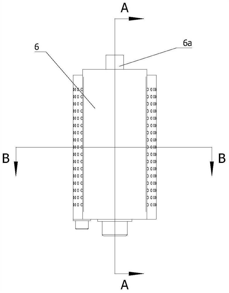
[0046] Such as Figure 4 and Figure 5 Shown:

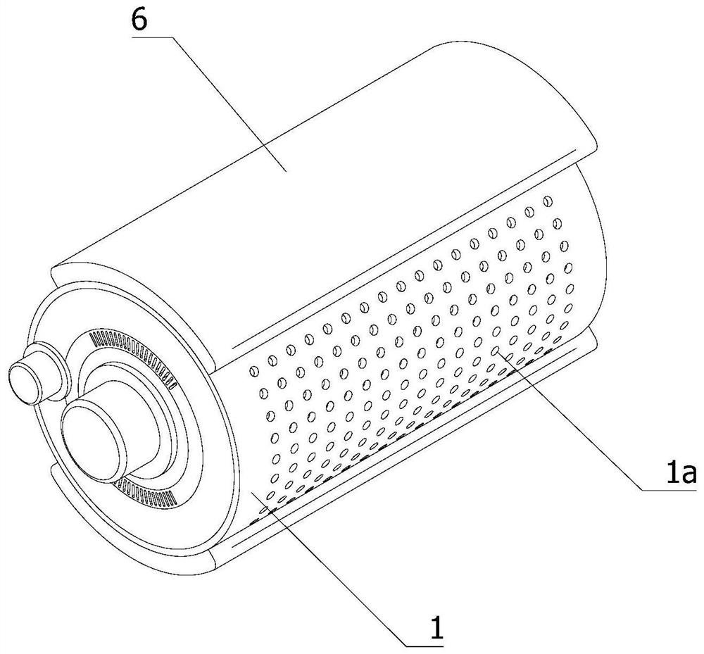
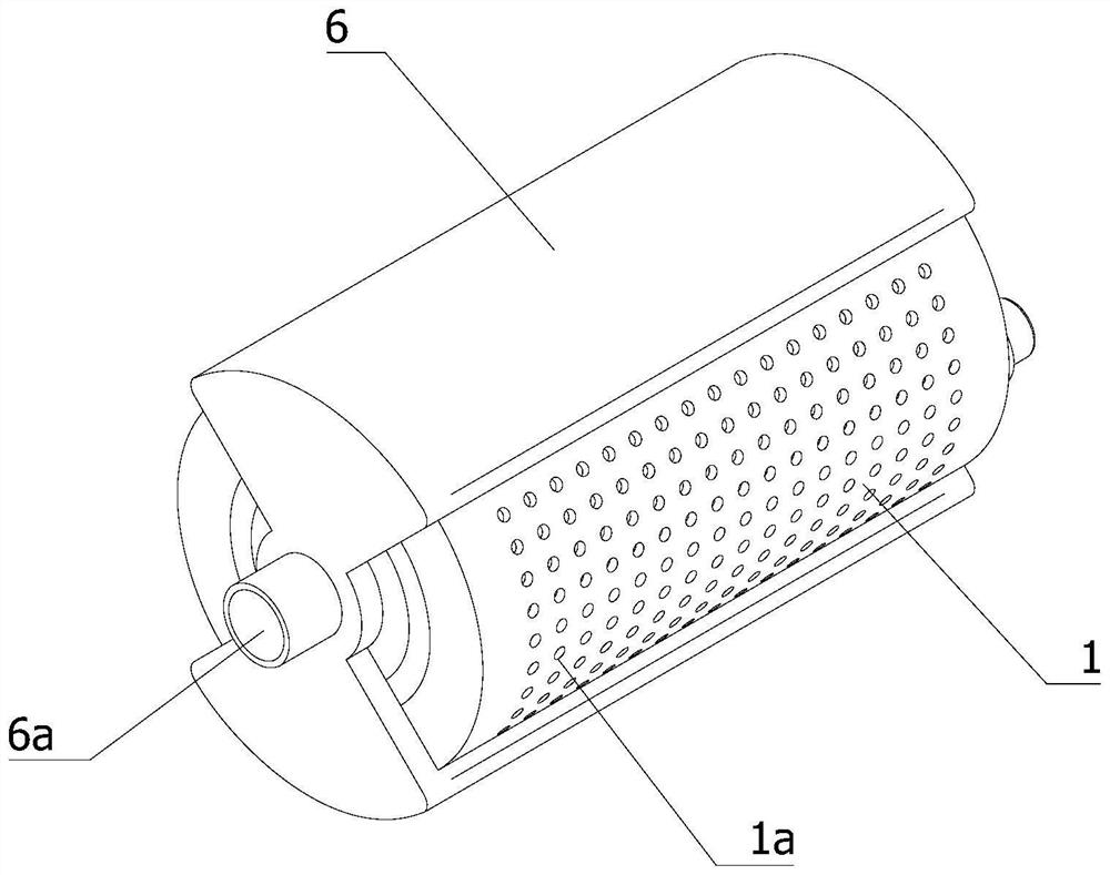
[0047] A drying device, including a body arranged between the area to be dehumidified and the atmosphere. The body is provided with a dehumidification part, a drying part, a drainage part and a material exchange unit. The interior of the dehumidification part and the drying part is filled with a desiccant. The exchange unit is used to exchange the inner filling of the dehumidification part and the drying part. The drainage part is arranged between the dehumidification part and the drying part. The dehumidification part, the drainage part and the drying part are connected in sequence. The drainage part is used to guide the airflow to self-dehumidify The ...


PUM


Abstract

The invention relates to the field of electrical equipment, in particular to a drying device which comprises a body arranged between an area to be dehumidified and the atmosphere, a dehumidification part, a drying part, a drainage part and a material exchange unit are arranged in the body, the dehumidification part and the drying part are filled with drying agents, and the material exchange unit is used for exchanging filler in the dehumidification part and the drying part. The dehumidification part and the drying part are arranged in the body, the drainage part is arranged between the dehumidification part and the drying part, the dehumidification part, the drainage part and the drying part are sequentially communicated, the drainage part is used for guiding airflow to flow to the drying part from the dehumidification part, the dehumidification part is communicated with the to-be-dehumidified area, and the drying part is communicated with the atmosphere. The drying agent in the dehumidification part and the drying part is exchanged through the material exchange unit, so that the dehumidification part can stably and continuously dehumidify, and the dried airflow can pass through the drying area to dry the humid drying agent in the drying area, so that the dehumidification part and the drying part continuously exchange the drying agent. The invention further relates to a split type power distribution cabinet with the drying device.

Description

technical field [0001] The invention relates to the field of electric equipment, in particular to a drying device. The invention also relates to a split type power distribution cabinet with a drying device. Background technique [0002] Power distribution cabinets (boxes) are divided into power distribution cabinets (boxes), lighting distribution cabinets (boxes), and metering cabinets (boxes), which are the final equipment of the power distribution system. The power distribution cabinet is a general term for the motor control center. The power distribution cabinet is used in the occasions where the load is relatively scattered and there are few circuits; the motor control center is used in the occasions where the load is concentrated and there are many circuits. They distribute the electric energy of a certain circuit of the upper-level power distribution equipment to the nearest load. This level of equipment shall provide protection, monitoring and control of the load. ...

Claims


Application Information

Patent Timeline
Patent Type & Authority Applications(China)
IPC IPC(8): B01D53/26H02B1/28
CPCB01D53/26H02B1/28
Inventor 李晓姜
Owner 李晓姜
Why Eureka
Try Eureka