Ceramsite particle forming device and forming method
A technology of particle forming and ceramsite, which is applied in chemical instruments and methods, solid separation, grain processing, etc., can solve the problems of rapid drying of particle forming, reduced performance, wet surface of particles, etc., to improve work efficiency and performance, The effect of improving performance and high molding quality
- Summary
- Abstract
- Description
- Claims
- Application Information
AI Technical Summary
Problems solved by technology
Method used
Image
Examples
Embodiment example 1
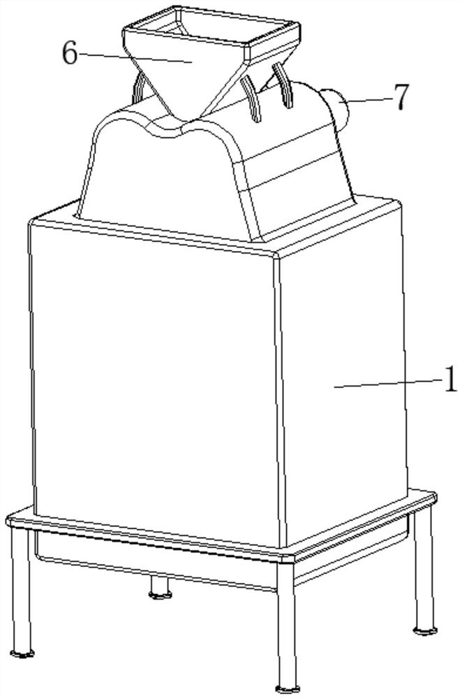
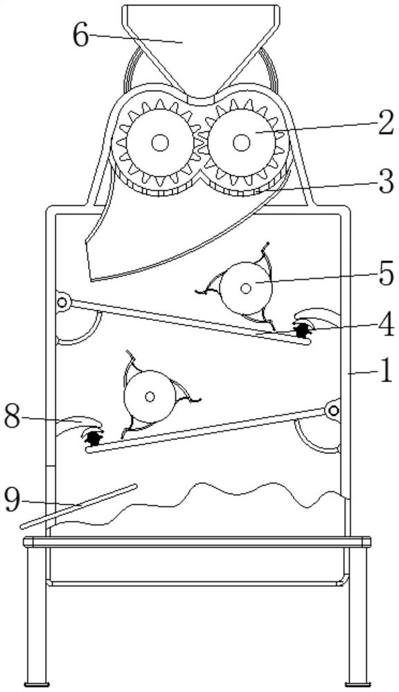
[0041] see Figure 1-7 , the present invention provides a technical solution: a ceramsite granule molding device, including a machine body 1, a molding roller 2, a sorting device 3, a screening device 4, and a toggle device 5, and the molding roller 2 is rotatably connected to the body 1 Inside and close to the top position, the sorting device 3 is set inside the machine body 1 and close to the profiling roller 2, the screening device 4 is set inside the machine body 1, and the toggle device 5 is set inside the machine body 1 and close to the screen The top position of moving device 4;
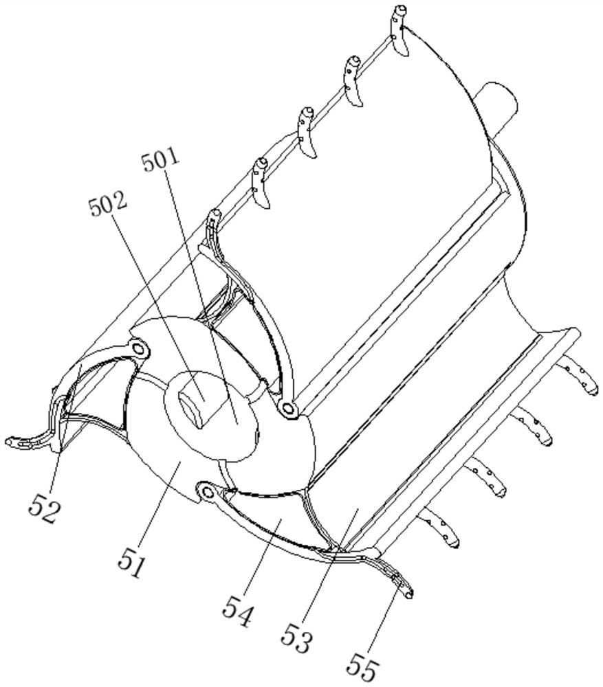
[0042] The top of the body 1 is provided with a feed hopper 6, one end of the profiling roller 2 penetrates the inner wall of the body 1 and extends to the outside, the top side of the body 1 is fixedly connected with a power mechanism 7, the output end of the power mechanism 7 is connected to the pressure One end of the forming roller 2 is fixedly connected, the inner wall of the body 1 and ...
Embodiment example 2
[0044] Sorting device 3 is provided with butterfly base plate 31, sorting hole 32, guide bucket 33, and the surface edge of butterfly base plate 31 is fixedly connected with the inner wall of body 1, and sorting hole 32 is offered on the surface of butterfly base plate 31, guides The top of the funnel 33 is fixedly connected to the bottom of the butterfly base plate 31 .
[0045] The sorting holes 32 are evenly distributed on the surface of the butterfly-shaped base plate 31, and the guide bucket 33 is arranged obliquely so that the discharge port is located on one side, and the butterfly-shaped base plate 31 is located at the bottom of the forming roller 2, which is helpful for crushing the ceramic raw materials Forming, and the qualified ceramsite particles are leaked through the sorting hole 32, and the large-grained ceramic raw materials continue to be broken, so that the particles are uniform, and the size of the slaves is different, so that the quality of the particles is...
Embodiment example 3
[0047] The sieving device 4 is provided with a screen 41, a curved skirt 42, an arc-shaped elastic reset member 43, and a buffer device 44. One end of the screen 41 is hinged to the inner wall of the body 1, and the curved skirt 42 is fixed on the top of the screen 41 and is close to the At the edge position, the arc-shaped elastic reset member 43 is arranged between the bottom of the screen 41 and the two sides corresponding to the inner wall of the body 1, the buffer device 44 is arranged on the top of the screen 41 and close to the curved skirt 42, and the drive roller 51 Drive the arc-shaped connecting plate 52 and the comb device 55 to rotate together, and then press the screen 41, and combine one end of the screen 41 with the inner wall of the body 1 to hinge, and utilize the elastic force of the arc-shaped elastic reset member 43, so that The sieve 41 reciprocates and uses the principle of inertia to shed moisture from the surface of the formed granules and promote the g...
PUM
 Abstract
Description
Claims
Application Information
 - R&D
- Intellectual Property
- Life Sciences
- Materials
- Tech Scout
- Unparalleled Data Quality
- Higher Quality Content
- 60% Fewer Hallucinations
Browse by: Latest US Patents, China's latest patents, Technical Efficacy Thesaurus, Application Domain, Technology Topic, Popular Technical Reports.
© 2025 PatSnap. All rights reserved.Legal|Privacy policy|Modern Slavery Act Transparency Statement|Sitemap|About US| Contact US: help@patsnap.com


