Anti-collision safety device for numerical control turning center

A safety device and turning technology, applied in the field of CNC machine tools, can solve the problems of poor use effect of anti-collision components, and achieve the effect of protection from damage

Active Publication Date: 2022-05-13
安徽新诺精工股份有限公司
View PDF17 Cites 0 Cited by
  • Summary
  • Abstract
  • Description
  • Claims
  • Application Information

AI Technical Summary

Problems solved by technology

[0006] The technical problem to be solved by the present invention is to provide an anti-collision safety device for CNC turning center to solve The problem of poor use effect of the anti-collision components of the machine tool

Method used


Image

  • Anti-collision safety device for numerical control turning center
  • Anti-collision safety device for numerical control turning center
  • Anti-collision safety device for numerical control turning center

Examples


Embodiment 2

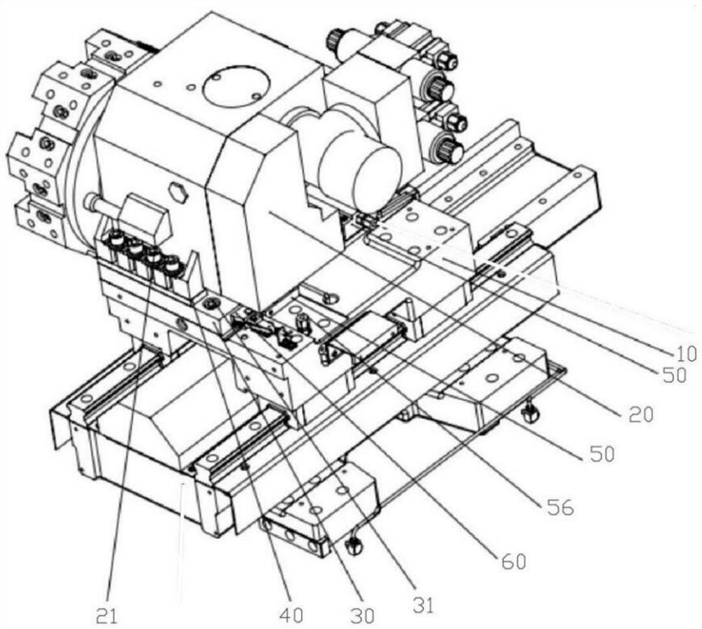
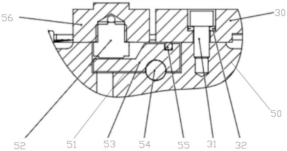
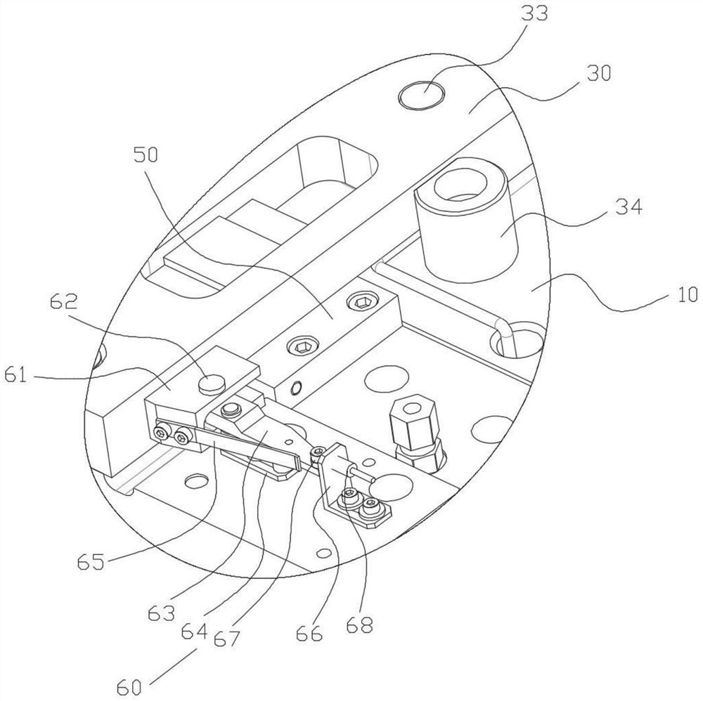
[0060] As an optimized solution of Embodiment 1, the induction component 60 includes

[0061] The coupling block 61 is arranged on the side wall of the transition plate 30;

[0062] The pointer 63 is rotatably connected to the coupling block 61 by pulling out the pin 62;

[0063] The rotating shaft seat 64 is arranged on the slide plate 10, and the pointer 63 is rotationally connected with the rotating shaft seat 64;

[0064] The sensor frame 66 is arranged on the slide plate 10;

[0065] Inductive switch 68 is arranged on the sensor frame 66;

[0066] The detection block 67 is arranged at the end of the pointer 63 , and the detection block 67 is used to detect the position change of the end of the pointer 63 .

[0067] This embodiment is implemented in this way, when there is a collision phenomenon, the position of the transition plate 30 will change; its slight variation is magnified by tens of times through the coupling block 61, the dial pin 62, and the pointer 63, and ...

Embodiment 3

[0069] As an optimized solution of the second embodiment, a spring piece 65 is further provided on the side wall of the coupling block 61 , and the spring piece 65 is in close contact with the pointer 63 .

[0070] This embodiment is implemented in this way, the same spring 65 gives a "pretension" to the pointer 63, so that the pointer 63 cannot swing freely, so as to avoid false alarms

Embodiment 4

[0072] As an optimized solution of the first embodiment, the sliding plate 10 is provided with a stopper 34 facing the side wall of the transition plate 30 .

[0073] This embodiment is implemented in such a way that the transition plate 30 is prevented from infinitely shifting position through the set stopper 34, that is, it plays the role of "dead stop iron". When the transition plate 30 hits it, in principle, it cannot Another position change.


PUM


Abstract

The invention discloses an anti-collision safety device for a numerical control turning center, which relates to the technical field of numerical control machine tools, and comprises a transition plate connected to a sliding plate through a second inner hexagon screw; wherein a belleville spring is sleeved on the inner hexagon screw; the servo tool rest penetrates through the adjusting pad through a first inner hexagon screw and is connected with the transition plate; the cylindrical pin is arranged on the sliding plate and penetrates through the transition plate in a sliding manner; the two oil supply plates are respectively embedded in the sliding plate; the positioning groove is formed in the oil supply plate; the pressure cylinders are respectively arranged on the oil supply plate; the top plate is placed in the positioning groove; the supporting shaft is located at the intersection of the top plate and the bottom of the positioning groove, and the top plate can rotate along the supporting shaft; the pin roller is embedded in the position, intersected with the transition plate, of the top plate, and the pin roller protrudes out of the surface of the top plate; the method has the advantages that the probability of collision loss can be greatly reduced, and the running safety of the machine tool is improved.

Description

technical field [0001] The invention relates to the technical field of numerical control machine tools, in particular to an anti-collision safety device for a numerical control turning center. Background technique [0002] CNC machine tools are high-efficiency, high-precision processing equipment with high overall value. Although the performance is constantly improving, crashes will occur due to improper programming, misoperation, or unforeseen interference between the tool and the workpiece, often resulting in large economic losses. [0003] The method of using ultrasonic or optical sensors to monitor the speed of moving parts, their distance from obstacles, and judge the tendency of collisions is expensive, complicated to use, and adaptable to the polluting environment caused by debris, coolant, etc. in the machine tool working area needs improvement. The existing machine tool numerical control system is also equipped with corresponding program inspection functions, such...

Claims


Application Information

Patent Timeline
Patent Type & Authority Applications(China)
IPC IPC(8): B23B25/04B23Q11/00
CPCB23B25/04B23Q11/00
Inventor 关晓勇胡明洪宫德海毕伟峰柳晓川杨笑东谢振涛齐延男汪庆群吴志丹
Owner 安徽新诺精工股份有限公司
Why Eureka
Try Eureka