Spherical casting drilling equipment

A technology for drilling equipment and castings, which is applied in the direction of drilling/drilling equipment, boring/drilling, metal processing equipment, etc. It can solve the problem of difficult clamping of spherical parts, increase the workload of operators, and cannot guarantee drilling Position and other issues, to achieve the effect of strengthening the clamping force, good economic benefits, and enhancing the clamping force

Pending Publication Date: 2022-05-13
李何怡
View PDF0 Cites 2 Cited by
  • Summary
  • Abstract
  • Description
  • Claims
  • Application Information

AI Technical Summary

Problems solved by technology

[0002] In the production process of castings, punching equipment is usually used to punch holes to facilitate subsequent processing of castings, but spherical parts are difficult to clamp, and special fixtures need to be made for them, and manual chip removal becomes difficult during the clamping process. Frequently, the workload of the operator is increased. Therefore, when the number of processing is small, the spherical parts are drilled with a general fixture. There are many disadvantages in using a general fixture. Not only can it not guarantee that the drilling position is within the error , and the efficiency is not high, so we propose a spherical casting drilling equipment to solve the above problems

Method used


Image

  • Spherical casting drilling equipment
  • Spherical casting drilling equipment
  • Spherical casting drilling equipment

Examples


Embodiment Construction

[0025] The following will clearly and completely describe the technical solutions in the embodiments of the present invention with reference to the accompanying drawings in the embodiments of the present invention. Obviously, the described embodiments are only some, not all, embodiments of the present invention. Based on the embodiments of the present invention, all other embodiments obtained by persons of ordinary skill in the art without making creative efforts belong to the protection scope of the present invention.

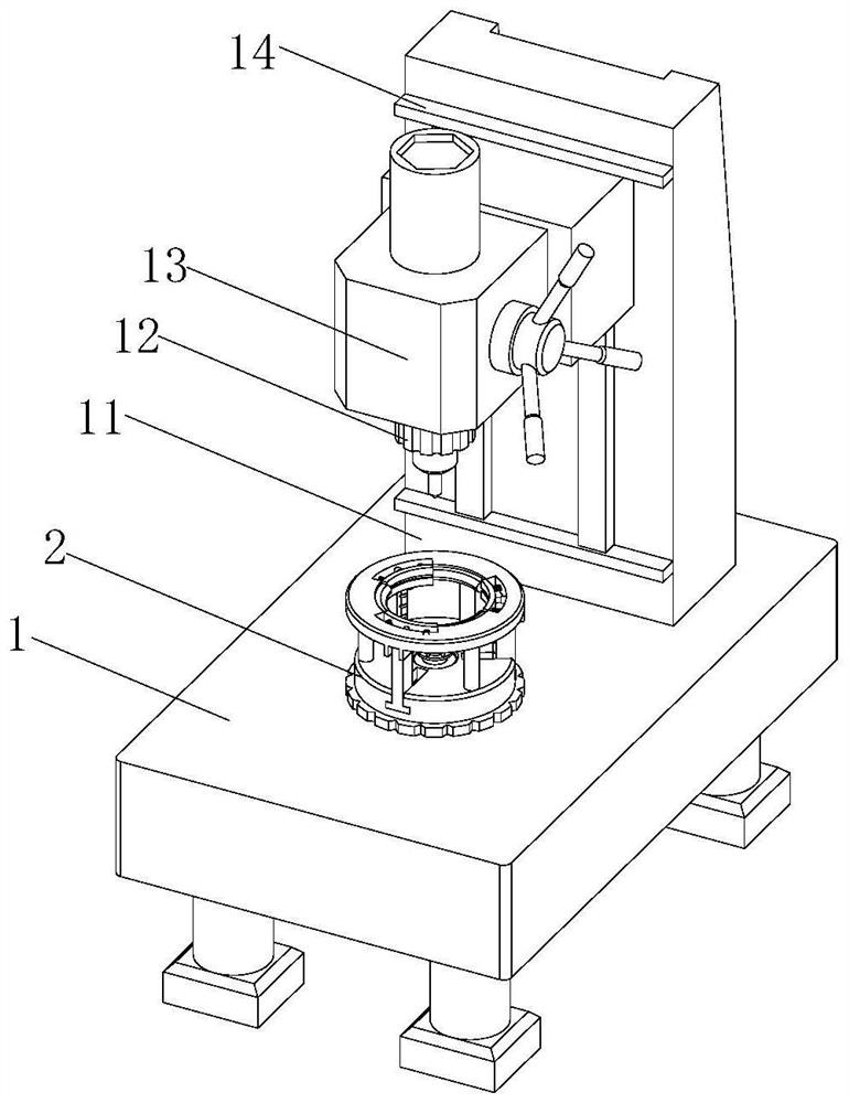
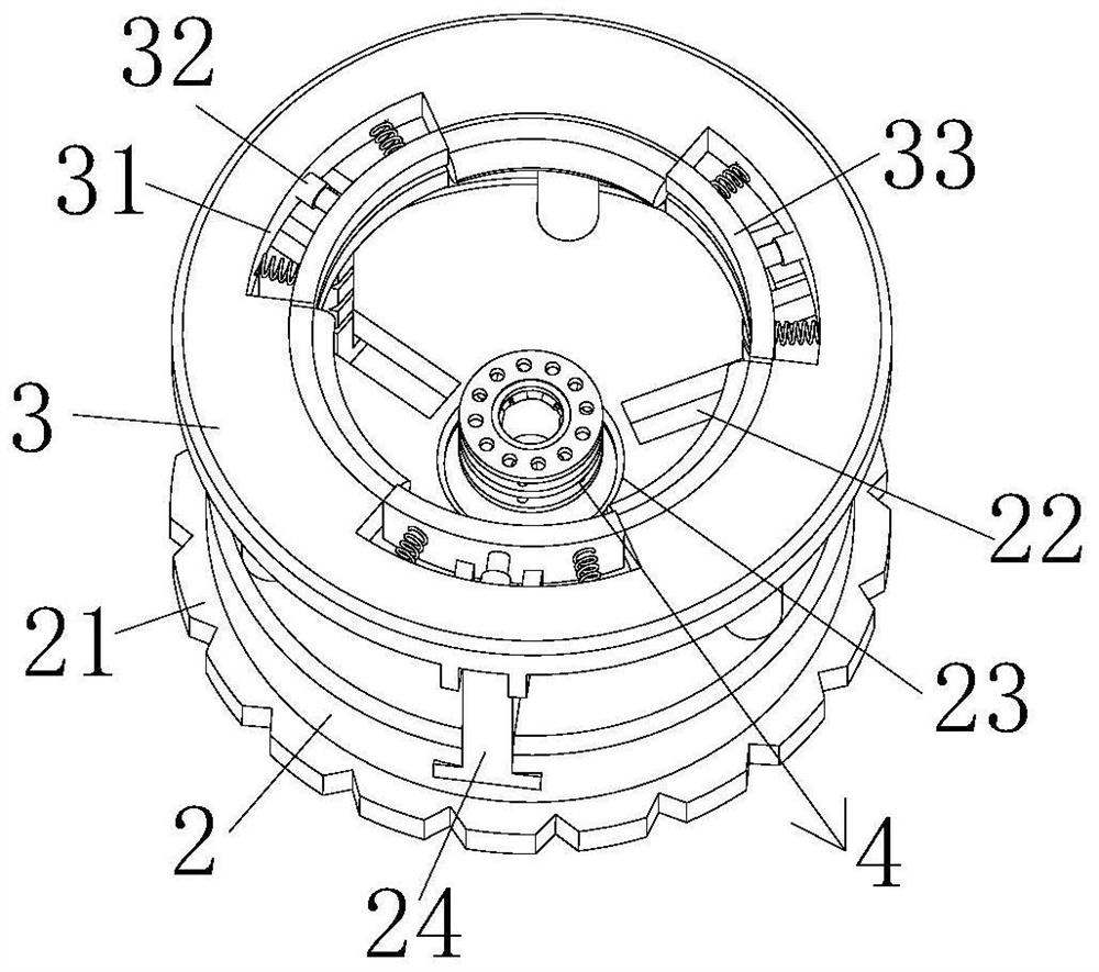
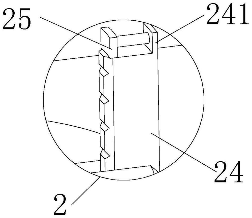
[0026] see Figure 1-6 , the present invention provides a technical solution: a spherical casting drilling equipment, including a fixed seat 1, the surface of the fixed seat 1 is fixedly connected with a connecting frame 11, the surface of the connecting frame 11 is fixedly connected with a pair of fixed rods, and the fixed rods Sliding is provided with movable table 13, and movable table 13 bottom is provided with rotating shaft, and dismantling drill bit 12 ...


PUM


Abstract

The invention discloses spherical casting drilling equipment which comprises a fixed seat, a connecting frame is fixedly connected to the surface of the fixed seat, a pair of fixed rods are fixedly connected to the surface of the connecting frame, a movable table is slidably arranged on the fixed rods, a rotating shaft is arranged at the bottom of the movable table, and a detachable drill bit is installed at the bottom of the rotating shaft. The surface of the connecting frame is fixedly connected with a pair of limiting plates, the limiting plates are located at the two ends of the fixing rod, one side of the connecting frame is provided with a clamping table, the clamping table is fixedly connected to the surface of the fixing base, and the surface of the clamping table is fixedly connected with a plurality of supporting vertical rods. The surface of a push plate can face one side of an arc-shaped extrusion plate, the arc-shaped extrusion plate can clamp a spherical casting, the surface of the spherical casting can extrude the surface of a movable plate, the movable plate can move, the contact area with the spherical casting can be increased, the clamping force on the casting can be further enhanced, and the stability during punching can be improved.

Description

technical field [0001] The invention relates to the technical field of metal processing, in particular to a spherical casting drilling equipment. Background technique [0002] In the production process of castings, punching equipment is usually used to punch holes to facilitate subsequent processing of castings, but spherical parts are difficult to clamp, and special fixtures need to be made for them, and manual chip removal becomes difficult during the clamping process. Frequently, the workload of the operator is increased. Therefore, when the number of processing is small, the spherical parts are drilled with a general fixture. There are many disadvantages in using a general fixture. Not only can it not guarantee that the drilling position is within the error , and the efficiency is not high, so we propose a spherical casting drilling equipment to solve the above problems. Contents of the invention [0003] The purpose of the present invention is to provide a spherical ...

Claims


Application Information

Patent Timeline
Patent Type & Authority Applications(China)
IPC IPC(8): B23B41/02B23B47/00B23Q3/06B23Q11/00B23Q11/10
CPCB23B41/02B23B47/00B23Q3/06B23Q11/10B23Q11/00B23Q11/0053
Inventor 李何怡
Owner 李何怡
Why Eureka
Try Eureka