Polishing machine for metal products and using method of polishing machine

A technology for metal products and polishing machines, applied in the field of mechanical processing, can solve the problems of staying in manual cleaning, and there is no device for stepping shaft burrs, etc., to improve processing efficiency, save tool replacement time, and have good oxidation resistance. Effect

Inactive Publication Date: 2022-05-13
重庆狼牙安防器材有限公司
View PDF1 Cites 0 Cited by
  • Summary
  • Abstract
  • Description
  • Claims
  • Application Information

AI Technical Summary

Problems solved by technology

[0005] Aiming at the above-mentioned deficiencies in the prior art, the present invention provides a polishing machine for metal products, which is used to solve the problem of manual deburring of stepped shafts with large end diameters and small middle diameters in the prior art. In the stage of cleaning, there is still no problem such as a device that can clean up the burrs of this stepped shaft, and the present invention also provides a method for using the device

Method used


Image

  • Polishing machine for metal products and using method of polishing machine
  • Polishing machine for metal products and using method of polishing machine
  • Polishing machine for metal products and using method of polishing machine

Examples


Embodiment 1

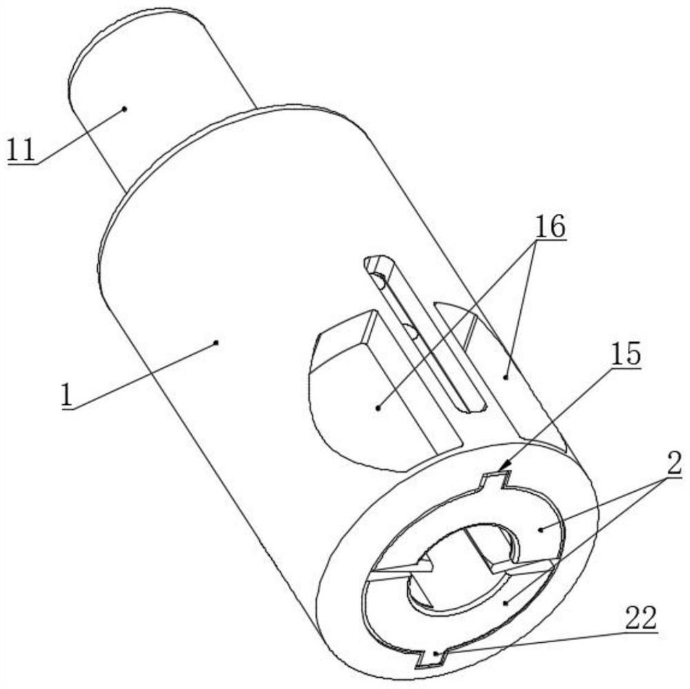
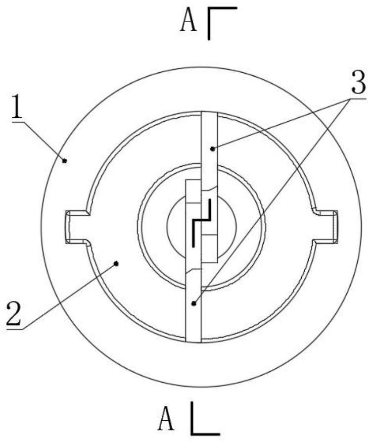
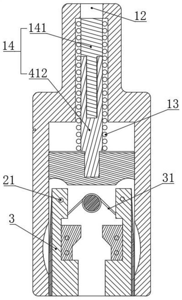
[0049] like Figure 1-7 As shown, a polishing machine for metal products includes a cylindrical knife barrel 1, a cylindrical support frame 2 installed inside the knife barrel 1 and axially slidably connected with it, and an outer shell mounted on the support frame 2. cutter 3;

[0050] The side wall of cutter barrel 1 is provided with through chip guide groove 16, and the upper end of outer cutter 3 is hinged with support frame 2, and the hinged part is hinge seat 21; Acting on the outer cutter 3, the lower end of the outer cutter 3 has a tendency to swing to the outside of the support frame 2.

[0051] The support frame 2 is two semi-cylindrical frame bodies, and the outer cutter 3 and the inner cutter 4 are all arranged between the two frame bodies. This design is convenient for the installation and maintenance of the outer cutter 3 and the inner cutter 4 . Axial slide block 22 is fixed on the outer wall of support frame 2, is provided with the chute 15 that slides with s...

Embodiment 2

[0065] This embodiment is a further improvement of the previous embodiment, such as Figure 1-7 As shown, a polishing machine for metal products includes a cylindrical knife barrel 1, a cylindrical support frame 2 installed inside the knife barrel 1 and axially slidably connected with it, and an outer shell mounted on the support frame 2. cutter 3;

[0066] The side wall of cutter barrel 1 is provided with through chip guide groove 16, and the upper end of outer cutter 3 is hinged with support frame 2, and the hinged part is hinge seat 21; Acting on the outer cutter 3, the lower end of the outer cutter 3 has a tendency to swing to the outside of the support frame 2.

[0067] The support frame 2 is two semi-cylindrical frame bodies, and the outer cutter 3 and the inner cutter 4 are all arranged between the two frame bodies. This design is convenient for the installation and maintenance of the outer cutter 3 and the inner cutter 4 . Axial slide block 22 is fixed on the outer w...


PUM


Abstract

The invention belongs to the technical field of machining, and particularly relates to a metal product polishing machine which comprises a cylindrical cutter cylinder, a cylindrical supporting frame installed in the cutter cylinder and axially connected with the cutter cylinder in a sliding mode, and an outer cutter installed on the supporting frame. The upper end of the outer cutter is hinged to the supporting frame, and a hinged support is arranged at the hinged position. A torsion spring is further installed on the supporting frame, the elastic force of the torsion spring acts on the outer cutter, the lower end of the outer cutter tends to swing towards the outside of the supporting frame, and the using method of the device comprises the steps of clamping, locking, burr cleaning and the like. The machine tool replaces people to provide torque to enable the inner cutter and the outer cutter to rotate, and the effect of cleaning burrs of the stepped shaft is achieved; meanwhile, the ejector rod with the adjustable length can control the clamping precision, adjust the inclination of the cutting edge of the outer cutter and adapt to the workpiece in an inclined plane shape, the outer cutter can be kept in an unfolded state, only the inner cutter works independently, and the adaptability to the machined workpiece is greatly improved.

Description

technical field [0001] The invention belongs to the technical field of mechanical processing, and in particular relates to a polishing machine for metal products and a using method thereof. Background technique [0002] In auto parts manufacturing and other manufacturing industries, after pipe fittings are machined, cut or injection molded, burrs will be generated on the cut and connected surfaces. According to the traditional deburring of the outer circle of the gear pump shaft sleeve, it cannot deal with the stepped shaft with a large diameter at the end and a small diameter at the middle. Regular and untidy in appearance. [0003] The patent with publication number CN106141323A discloses a deburring cleaner, which includes a movable shaft and a connecting body. The rear section of the movable shaft is provided with an annular retaining ring, and a flow hole is arranged between two adjacent annular retaining rings. There is a ring-shaped knife seat; blades are distribute...

Claims


Application Information

Patent Timeline
Patent Type & Authority Applications(China)
IPC IPC(8): B23P9/00
CPCB23P9/00
Inventor 杨阳况巧李新莲况锡洪李威霆李家豪
Owner 重庆狼牙安防器材有限公司
Why Eureka
Try Eureka