Pneumatic hydraulic clamp with pressurizing locking and pressure maintaining functions

A pneumatic, hydraulic and functional technology, applied in the direction of clamping, manufacturing tools, workpiece clamping devices, etc., can solve problems such as reducing work efficiency, losing parts to be processed, and losing power sources for fixtures, improving work efficiency and simplifying the operation process. Effect

Active Publication Date: 2022-05-13
武汉晟隆鼎科技有限公司
View PDF10 Cites 1 Cited by
  • Summary
  • Abstract
  • Description
  • Claims
  • Application Information

AI Technical Summary

Problems solved by technology

[0004] Aiming at the deficiencies of the prior art, the present invention provides a pneumatic hydraulic clamp with its own pressurized locking and pressure maintaining functions, which solves the problem that the parts to be processed have different thickness specifications and cannot be directly placed between the clamp and the console. The work efficiency is reduced and the hydraulic oil pipe is prone to breakage under high-pressure conditions. The breakage of the hydraulic oil pipe will easily cause the fixture to lose its power source and lose the limit of the parts to be processed. The problem of safety accidents is prone to occur in the case of

Method used


Image

  • Pneumatic hydraulic clamp with pressurizing locking and pressure maintaining functions
  • Pneumatic hydraulic clamp with pressurizing locking and pressure maintaining functions
  • Pneumatic hydraulic clamp with pressurizing locking and pressure maintaining functions

Examples


Embodiment Construction

[0026] The following will clearly and completely describe the technical solutions in the embodiments of the present invention with reference to the accompanying drawings in the embodiments of the present invention. Obviously, the described embodiments are only some, not all, embodiments of the present invention. Based on the embodiments of the present invention, all other embodiments obtained by persons of ordinary skill in the art without making creative efforts belong to the protection scope of the present invention.

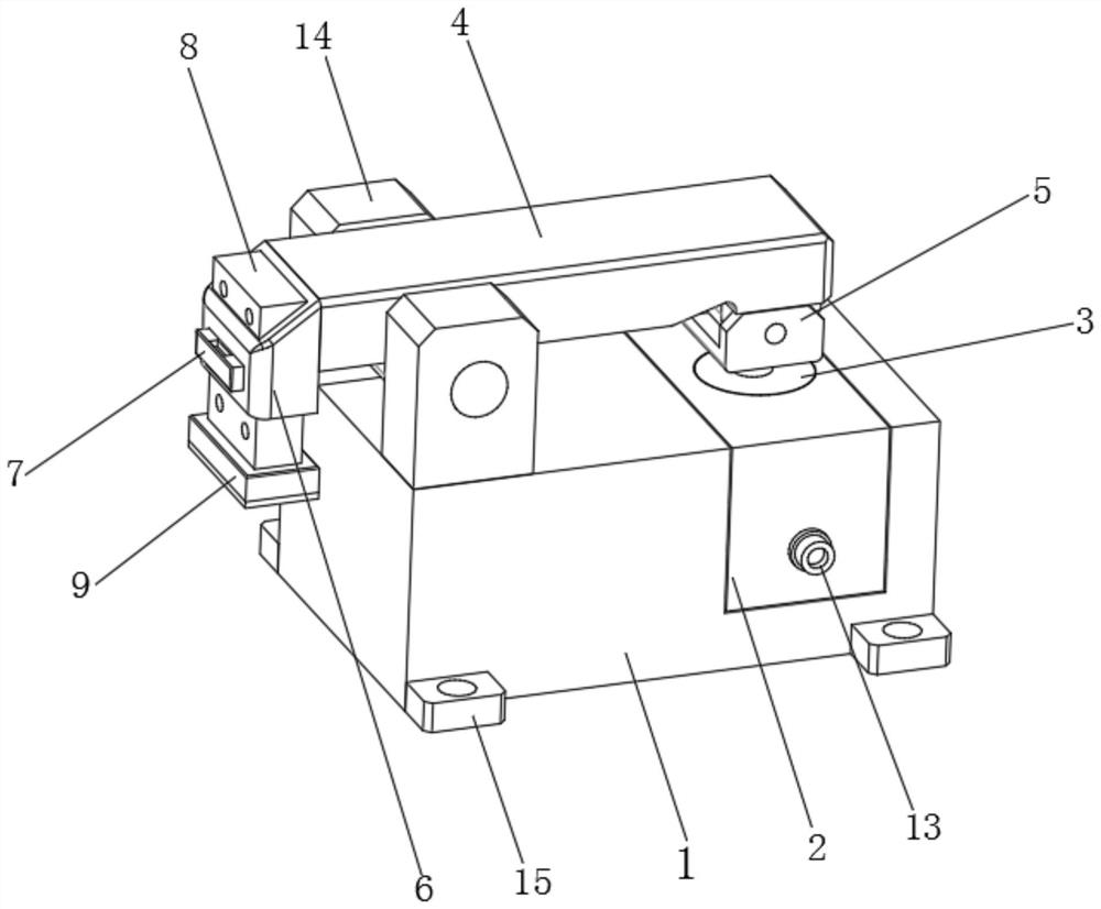
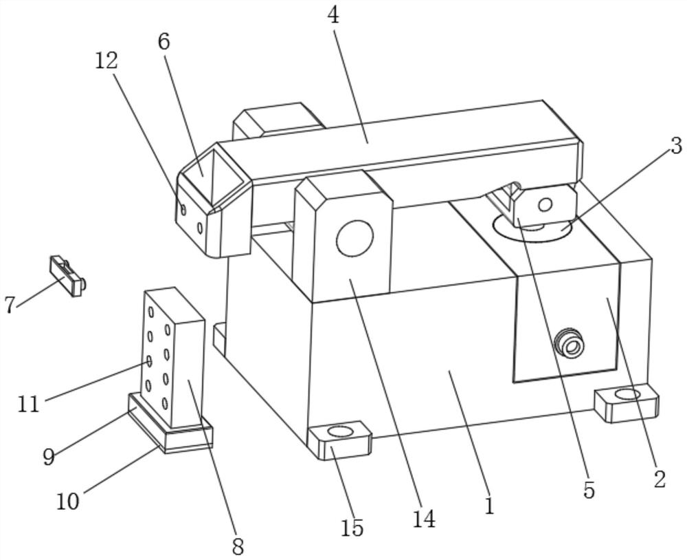
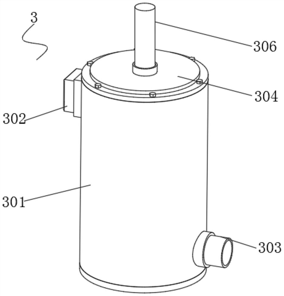
[0027] see Figure 1-5, the present invention provides a technical solution: a pneumatic hydraulic clamp with its own pressurized locking and pressure maintaining functions, including a base 1, a transmission box 2, a power assembly 3 and a pressure arm 4, the top side of the base 1 There is an installation slot, and the inside of the installation slot is fixed with a transmission box 2, and the inside of the transmission box 2 is fixed with a power assembly 3...


PUM


Abstract

The invention discloses a pneumatic hydraulic clamp with pressurization locking and pressure maintaining functions, and relates to the technical field of clamps, the pneumatic hydraulic clamp comprises a base, a transmission box, a power assembly and a pressure arm, an adjusting plate is arranged at the left end of the pressure arm, and before a part is placed on a machining table, the height of the adjusting plate can be adjusted according to the thickness of the part to be machined; according to the clamp device, the pressing head is arranged on the machining table, so that a part can be conveniently placed between the machining table and the pressing head, backing plates do not need to be repeatedly added or reduced at the bottom of the clamp device, the operation process is simpler, and the working efficiency is greatly improved; second hydraulic oil on the movable set partition plate can enter the bottom of the piston through the hole, the piston is jacked by the hydraulic oil, when oil supply in the hydraulic oil tank is stopped, the movable partition plate is pulled back to the original position by the reset spring, a closed state is formed between the piston and the hydraulic oil tank, and the effect of continuously jacking the piston is achieved.

Description

technical field [0001] The invention relates to the technical field of clamps, in particular to a pneumatic hydraulic clamp with its own pressurized locking and pressure maintaining functions. Background technique [0002] The fixture is a device used to fix the processing object in the process of mechanical manufacturing so that it can occupy the correct position to accept construction or inspection, also known as fixture. In a broad sense, any process in the process, the device used to install the workpiece quickly, conveniently and safely, can be called a fixture. Such as welding fixtures, inspection fixtures, assembly fixtures, machine tool fixtures, etc. Among them, machine tool fixtures are the most common, often referred to as fixtures. The hydraulic fixture is a fixture that uses hydraulic components instead of mechanical parts, and realizes automatic positioning, support and clamping of the workpiece through hydraulic control. It has the advantages of large clamp...

Claims


Application Information

Patent Timeline
Patent Type & Authority Applications(China)
IPC IPC(8): B23Q3/08B25B11/00
CPCB23Q3/082B25B11/00
Inventor 田启泉符杰
Owner 武汉晟隆鼎科技有限公司
Why Eureka
Try Eureka