Pelletizing cutter set device for twin-screw extruder

A twin-screw extruder, pelletizing technology, applied in metal processing and other directions

Active Publication Date: 2022-07-22
金纬机械(海宁)有限公司
View PDF3 Cites 0 Cited by
  • Summary
  • Abstract
  • Description
  • Claims
  • Application Information

AI Technical Summary

Problems solved by technology

[0005] The object of the present invention is to provide a kind of pelletizing cutter disc unit device of a twin-screw extruder, to solve the problems of the shortcomings of the prior art in the above-mentioned background technology

Method used


Image

  • Pelletizing cutter set device for twin-screw extruder
  • Pelletizing cutter set device for twin-screw extruder
  • Pelletizing cutter set device for twin-screw extruder

Examples


Embodiment Construction

[0033] The technical solutions in the embodiments of the present invention will be clearly and completely described below with reference to the accompanying drawings in the embodiments of the present invention. Obviously, the described embodiments are only a part of the embodiments of the present invention, rather than all the embodiments. Based on the embodiments of the present invention, all other embodiments obtained by those of ordinary skill in the art without creative efforts shall fall within the protection scope of the present invention.

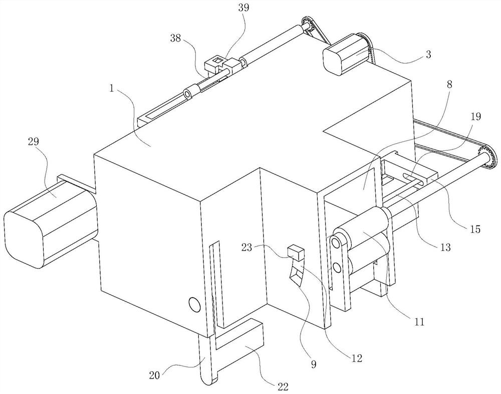
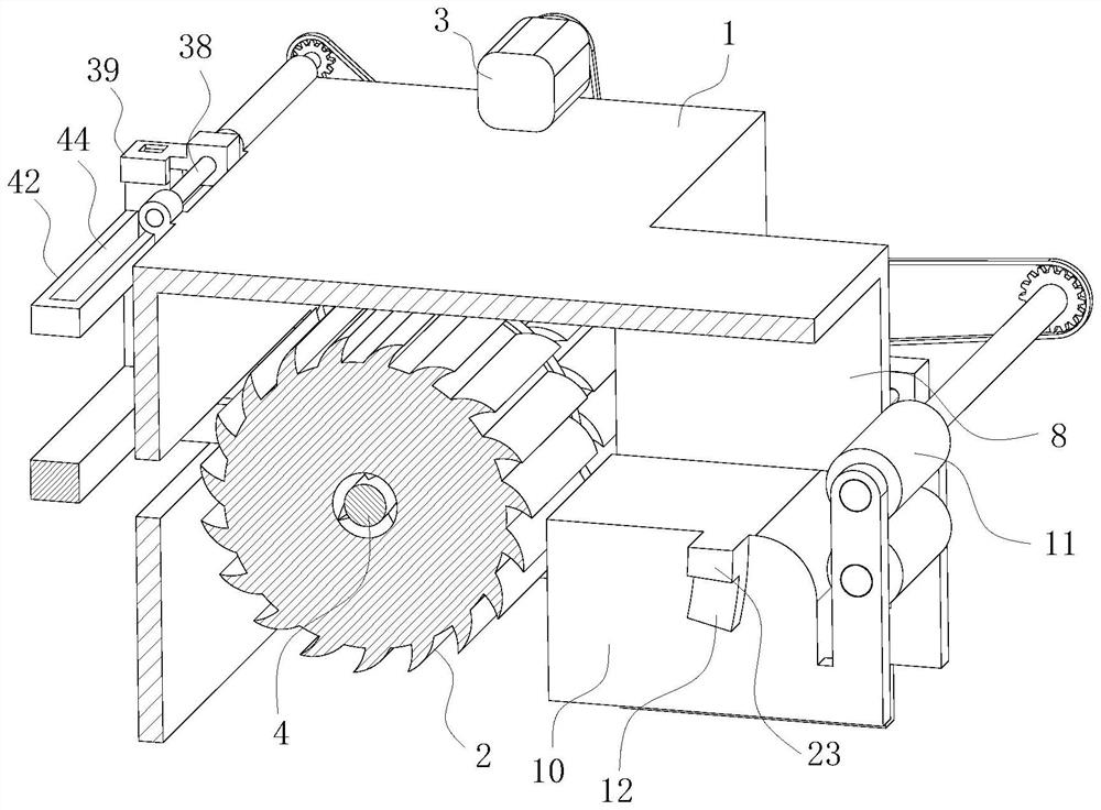
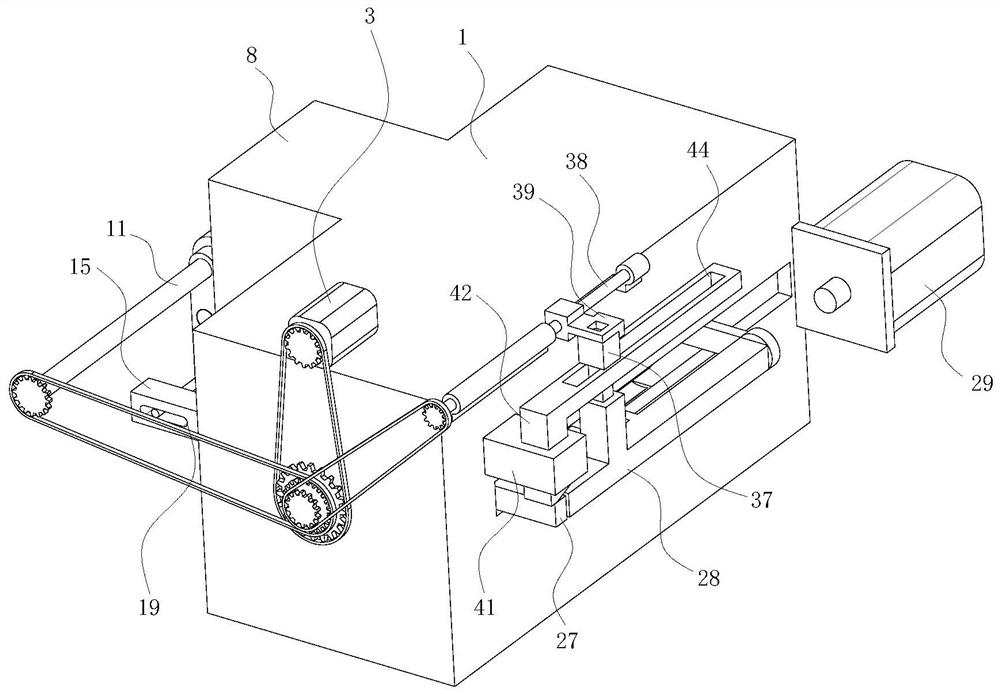
[0034] see Figure 1-11, the present invention provides a technical solution: including a casing 1, a main hob 2, a feeding assembly for feeding, a drive motor 3 for driving the feeding assembly and the main hob 2, and a spare hob unit, the machine The rear end of the casing 1 is rotatably installed with a rotating shaft 4. The front end of the rotating shaft 4 extends into the inner cavity of the casing 1. The main hob 2 and the spa...


PUM


Abstract

The invention discloses a pelletizing cutter set device of a twin-screw extruder in the technical field of extruder pelletizing, comprising a casing, a main hob, a feeding component for feeding, and a feeding component for driving the feeding And the drive motor of the main hob and the spare hob, the rear end of the casing is rotatably installed with a rotating shaft, the front end of the rotating shaft extends into the inner cavity of the casing, the rear end surface of the rear push plate is fixedly installed with an energy storage spring, and the rear end of the energy storage spring is connected to the inner cavity of the casing. The rear end of the inner cavity of the casing is fixedly connected, the rear side of the right end face of the casing is installed with a locking component for locking the rear push plate, the right end face of the casing is provided with a feeding port, and the inner front and rear faces of the feeding port are provided with sliding grooves. The invention can determine the wear condition of the main hob according to the force of the feeding table, and can find the wear condition of the main hob in time. the quality of production.

Description

technical field [0001] The invention relates to the technical field of pelletizing of an extruder, in particular to a pelletizing cutter disk group device of a twin-screw extruder. Background technique [0002] Extrusion molding is to make the melt (or viscous fluid) of the polymer pass through a certain shape of the die under the extrusion action of the extruder screw, and the product is a continuous profile with a constant cross-sectional shape. At the exit of the extruder, the profile extruded by the extruder is fed into the inner cavity of the cutter head group through the feeding roller, and then the extruded profile is cut into equal distances by the high-speed rotating hob. [0003] The granulating hob in the dicing cutter disc group will wear out during use, and the contact area between the dicing hob and the cut surface of the profile will increase after the knife edge is worn, which will cause the particles after dicing. There is a deviation in the length, and the...

Claims


Application Information

Patent Timeline
Patent Type & Authority Patents(China)
IPC IPC(8): B29B9/06B26D7/26
CPCB29B9/06B26D7/2614
Inventor 楼亦剑何海潮唐鹏圆
Owner 金纬机械(海宁)有限公司
Why Eureka
Try Eureka