Finish machining equipment for surface of die steel and finish machining process of finish machining equipment

A technology of mold steel and equipment, applied in the field of finishing equipment on the surface of mold steel, can solve the problems of slow gas flow, inability to effectively absorb shoe boxes, and reduce the practicability of shoe boxes

Pending Publication Date: 2022-02-15
湖北友鑫模具材料股份有限公司
View PDF0 Cites 0 Cited by
  • Summary
  • Abstract
  • Description
  • Claims
  • Application Information

AI Technical Summary

Problems solved by technology

[0005] In order to overcome the deficiencies of the existing technology, a finishing equipment for the surface of mold steel is proposed, which solves the problem that the existing sterilization and deodorization multi-functional intelligent environmental protection plastic shoe boxes are damaged by the ultraviolet light in the shoe box during use. Sterilize, and the purple light is located on the outside of the shoes, which cannot effectively sterilize the inside of the shoes and reduce the practicability of the shoe box. Secondly, the existing sterilizing and deodorizing multifunctional intelligent environmental protection plastic shoe boxes are absorbed by the air holes and activated carbon during use. The board adsorbs the peculiar smell of the shoes. During the adsorption, the flow rate of the gas is slow, which causes the activated carbon adsorption board to be unable to effectively absorb the peculiar smell in the shoe box and reduce the work efficiency. During use, the shoes cannot be fixed, and there are differences in the size of the shoes, which may easily cause the shoes to shift in the shoe box, making it inconvenient to use

Method used


Image

  • Finish machining equipment for surface of die steel and finish machining process of finish machining equipment
  • Finish machining equipment for surface of die steel and finish machining process of finish machining equipment
  • Finish machining equipment for surface of die steel and finish machining process of finish machining equipment

Examples


Embodiment Construction

[0035] The present invention will be further described below in conjunction with accompanying drawing:

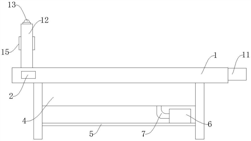
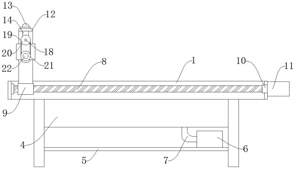
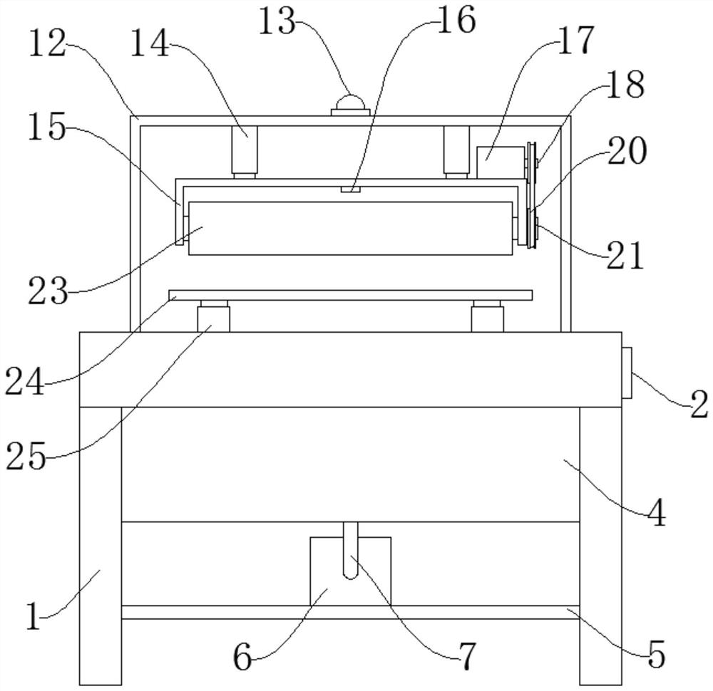
[0036] like Figure 1-Figure 4As shown, a finishing equipment for the surface of mold steel includes a frame 1, a threaded shaft 8 and a support frame 12. An operation panel 2 is installed on one side of the frame 1, and the staff can use the operation panel 2 to pair the device For control, the upper middle part of the frame 1 is fixed with a load-bearing grid 3, the load-bearing grid 3 can carry the mold steel, and a collection box 4 is installed under the frame 1, and the polished debris passes through the load-bearing Holes on the grille 3 fall into the collection box 4 for collection, and a support plate 5 is fixed below the collection box 4, and the support plate 5 can support the fan 6. On the support plate 5 A blower fan 6 is installed, and the blower blower 6 can extract debris. One side of the blower blower 6 is connected with a suction pipe 7, and the suction pi...


PUM


Abstract

The invention discloses a finish machining equipment for surface of die steel and finish machining process of finish machining equipment. The equipment comprises a rack, a threaded shaft and a supporting frame, an operation panel is installed on one side of the rack, a bearing grating is fixed to the upper middle portion of the rack, a collecting box is installed below the rack, a supporting plate is fixed to the lower portion of the collecting box, a draught fan is installed on the supporting plate, and one side of the draught fan is connected with a material pumping pipe. The equipment has the advantages that the equipment is novel in structure and convenient to operate, a laser range finder and a warning lamp are arranged, the distance between a polishing roller and a mounting frame support can be detected through the laser range finder, then early warning is conducted on workers through the warning lamp, and the workers can conveniently find out abrasion of the polishing roller in time; the damage to die steel caused by serious abrasion of the polishing roller is avoided, the product quality is guaranteed, the draught fan and the material pumping pipe are arranged, the draught fan can extract chippings in the collecting box through the material pumping pipe, workers can conveniently collect the chippings, and the working intensity of the workers is reduced.

Description

technical field [0001] The invention relates to the technical field of finishing equipment for die steel surfaces, in particular to a finishing equipment for die steel surfaces and a finishing process thereof. Background technique [0002] Die steel is used to manufacture cold stamping dies, hot forging dies, die-casting dies and other steel types. The quality of the die directly affects the quality of the pressure processing process, the accuracy of the product, and the production cost. The quality and service life of the die depend on In addition to reasonable structural design and processing accuracy, it is mainly affected by mold materials and heat treatment. [0003] During the use of the existing finishing equipment on the surface of the mold steel, the surface of the mold steel is finished by the polishing roller, and the polishing roller is in use, and the staff cannot check the wear condition of the polishing roller in time, resulting in serious wear of the polishin...

Claims


Application Information

Patent Timeline
IPC IPC(8): B24B29/02B24B41/04B24B41/06B24B47/22B24B49/12B24B55/06B24B55/12
CPCB24B29/02B24B41/04B24B41/06B24B55/12B24B55/06B24B47/22B24B49/12
Inventor 张云友
Owner 湖北友鑫模具材料股份有限公司
Why Eureka
Try Eureka