Intelligent flue energy recycling system

An energy recovery and energy collection technology, applied in waste heat treatment, furnaces, furnace control devices, etc., can solve problems such as production blockage, economic loss, flue blockage, etc., to save energy, protect the environment, and improve service life.

Active Publication Date: 2015-09-02
泰州金泰环保热电有限公司
View PDF5 Cites 0 Cited by
  • Summary
  • Abstract
  • Description
  • Claims
  • Application Information

AI Technical Summary

Problems solved by technology

Under normal circumstances, the ambient temperature of the flue is high, the flue gas is dry, high temperature, and high flow rate, so the water pipe on the windward side of the transducer tube wears quickly. When the transducer tube leaks trachoma or cracks, the internal water seeps or sprays out. Vaporize immediately in this high-temperature environment, and the vaporized water mist will deposit dust in the flue gas, thereby causing the flue to be blocked. Once the flue is blocked, production will be hindered, causing serious economic losses.

Method used


Image

  • Intelligent flue energy recycling system
  • Intelligent flue energy recycling system
  • Intelligent flue energy recycling system

Examples


Embodiment 1

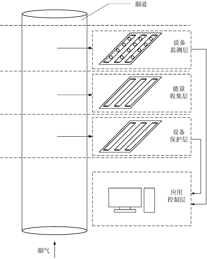
[0027] like figure 1 It is a structural schematic diagram of an embodiment of an intelligent flue energy recovery system of the present invention, including an energy collection layer for waste heat collection, an equipment protection layer for protecting the transducer tube, and equipment monitoring for detecting the working state of the transducer tube layer and an application control layer for collecting information and controlling; wherein, the device protection layer is located at the bottom of the system close to the flue, the energy collection layer is located on the upper part of the device protection layer, and the device monitoring layer is located on the upper part of the energy collection layer, the application control layer is located in the control room outside the flue, and the equipment protection layer and the equipment monitoring layer are electrically connected to the application control layer.

Embodiment 2

[0029] On the basis of Embodiment 1, further, the application control layer includes a signal acquisition unit and a server unit, and the signal acquisition unit is used to collect signals of the equipment protection layer and the equipment monitoring layer, and send the signals to the server unit, and the server unit includes a A computer, the server unit displays the status of the sensor of the device protection layer and the device detection layer. When the status of the sensor of the device protection layer or the device detection layer is abnormal, the server unit will indicate the fault area and prompt for maintenance.

[0030] The energy collection layer includes at least one layer of transduction tube network. The transduction tube network is composed of several transduction tubes, which can be composed of a square network formed in parallel.

[0031] The equipment protection layer includes a protection tube network and a protection tube monitoring unit. The protection ...

Embodiment 3

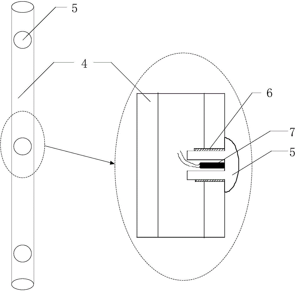
[0037] On the basis of embodiment 2, further, such as image 3 It is a schematic diagram of an embodiment of the second protection tube. The second protection tube includes a second protection tube body 4, several hollow screws 5, several screw holes 6 and several thermocouples 7, and the thermocouples 7 are fixed in the hollow with thermally conductive silica gel. Inside the screw 5, the hollow screw 5 is fixed in the screw hole 6, and the wire of the thermocouple 7 is electrically connected to the signal acquisition unit of the application control layer along the inside of the second protection tube. The hollow screw 5 is made of steel, which has good thermal conductivity, is abundant in the market, is relatively cheap, and is easy to process; of course, other metal materials such as aluminum, copper or silver can also be used.

[0038] Under normal circumstances, the temperature in the flue is higher than 100 degrees Celsius, so the leaked moisture will be vaporized in an i...


PUM


Abstract

The invention belongs to the technical field of energy utilization and particularly relates to intelligent flue energy recycling system which comprises an energy collection layer, an equipment protection layer, an equipment monitoring layer and an application control layer, wherein the energy collection layer is used for collecting waste heat; the equipment protection layer is used for protecting a transduction pipe; the equipment monitoring layer is used for detecting the working state of the transduction pipe; the application control layer is used for collecting information and controlling; the energy collection layer comprises at least one layer of transduction pipe network; the equipment protection layer comprises a protection pipe network and a protection pipe monitoring network; the equipment monitoring layer comprises a sensor network and a sensor protection network; the application control layer comprises a signal acquisition unit and a server unit. <}0{>By virtue of the energy collection layer, waste heat energy can be recovered; further by virtue of the equipment protection layer, the transduction pipe is protected; further, the equipment protection layer also has self abrasion detection capability and can discover existing hidden troubles in time; by virtue of the equipment monitoring layer, the working state of the transduction pipe can be monitored in real time, faults are discovered in time, and serious results are prevented from being caused.

Description

technical field [0001] The invention belongs to the technical field of energy utilization, and in particular relates to an intelligent flue energy recovery system. Background technique [0002] Instruments or devices used to realize the mutual conversion of different forms of energy can be collectively referred to as transducers, such as converting audio electrical signals into audible sound, or converting audible sound into audio electrical signals to realize the mutual conversion of electrical energy and sound energy. Electroacoustic transducers, such as loudspeakers (horns), earphones, microphones, etc. Heat exchanger, also known as heat exchanger, is also a kind of energy converter. It has the characteristics of small heat transfer resistance and large heat transfer capacity through enhanced heat transfer measures. It is the key equipment for rational use and saving of existing energy and development of new energy. Widely used in industries such as petroleum, chemical i...

Claims


Application Information

Patent Timeline
Patent Type & Authority Applications(China)
IPC IPC(8): F27D17/00F27D19/00
Inventor 李平朱为民
Owner 泰州金泰环保热电有限公司
Why Eureka
Try Eureka