
Distributed turnout control system for rail vehicle

A control system and distributed technology, which is applied in the field of rail transit, can solve the problems of affecting the appearance of the city along the urban rail line, the large size of relay logic, and waste of resources, so as to reduce the time and cost of upgrading and maintenance, and improve reliability and safety Sexuality and the effect of reducing project cost

Pending Publication Date: 2022-05-13
CRSC RESEARCH & DESIGN INSTITUTE GROUP CO LTD
View PDF7 Cites 0 Cited by
  • Summary
  • Abstract
  • Description
  • Claims
  • Application Information

AI Technical Summary

Problems solved by technology

The control methods of the current rail vehicle turnout control system are mainly centralized control and trackside control, but there are certain defects.
The centralized control method has certain requirements on the calculation amount of the center, and a large number of optical cables or cables need to be laid along the track, resulting in a waste of resources and affecting the appearance of the city along the urban track; A series of disadvantages of the high level make the turnout control system of the centralized control mode high in cost, high in failure rate, and heavy maintenance workload; in the decentralized control mode, the equipment is scattered, large in size, and has many modules, which increases the amount of engineering and investment
No matter which control method the current turnout control system is based on, the turnout execution layer adopts electrical centralized relay circuits, and the relay logic is large in size, with many wirings, high failure rate, and inconvenient for construction and maintenance.

Method used


Image

  • Distributed turnout control system for rail vehicle
  • Distributed turnout control system for rail vehicle
  • Distributed turnout control system for rail vehicle

Examples


Embodiment Construction

[0061] In order to make the purpose, technical solutions and advantages of the embodiments of the present invention more clear, the technical solutions in the embodiments of the present invention will be clearly and completely described below in conjunction with the accompanying drawings in the embodiments of the present invention. Obviously, the described embodiments It is a part of embodiments of the present invention, but not all embodiments. Based on the embodiments of the present invention, all other embodiments obtained by persons of ordinary skill in the art without making creative efforts belong to the protection scope of the present invention.

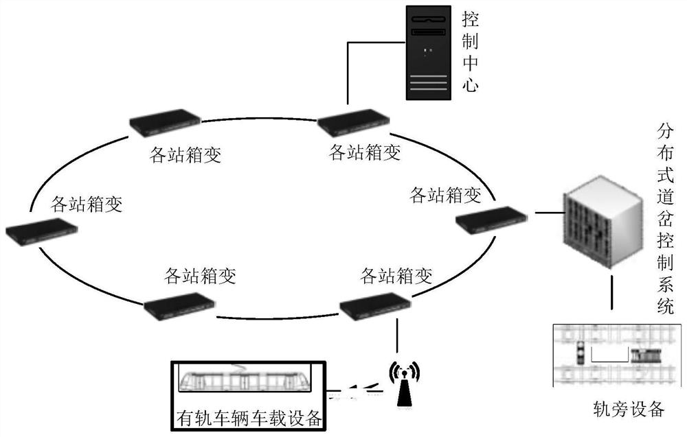
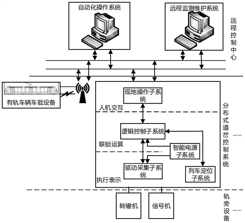
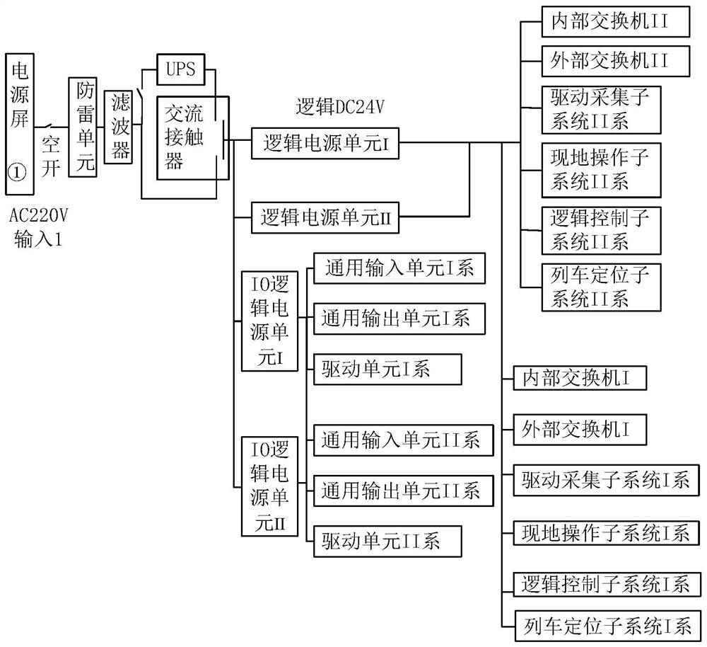
[0062] The distributed turnout control system is responsible for the interlock logic operation of the rail vehicle control system. A set of control system for the safety linkage relationship between track sections, turnouts, turnout indicators and other facilities on the road. Such as figure 1 As shown, the distributed turno...


PUM


Abstract

The invention discloses a distributed turnout control system for a rail vehicle. The distributed turnout control system comprises a logic control subsystem and a drive acquisition subsystem, the logic control subsystem is connected with the drive acquisition subsystem; the logic control subsystem is of a double-system redundant structure design and performs interlocking logic operation according to an operation command and a trackside equipment state; the driving and collecting subsystem is designed to be of a double-system redundant structure and is used for driving trackside equipment and collecting the state of the trackside equipment. The distributed turnout control system integrates safety interlocking logic operation, equipment driving acquisition, in-situ operation, train positioning and a power supply, and is high in expandability, high in flexibility and comprehensive in function; indexes such as voltage, current, temperature and standby power supply electric quantity can be monitored in real time; closed-loop control of driving, collecting and monitoring is achieved, and reliability and safety are improved. Turnout control equipment is arranged on site, and use of signal cables is reduced.

Description

technical field [0001] The invention belongs to the technical field of rail transit, in particular to a distributed turnout control system for rail vehicles. Background technique [0002] As a kind of urban rail transit, rail vehicles have developed rapidly in various countries in recent years. New-type rail vehicles are favored by various cities due to their clean energy, higher transportation speed than public transportation, and far lower cost than subways. For the rail vehicle signaling system, the research and development of signaling system equipment started late, and there is no unified standard to regulate the rail vehicle signaling system, and the turnout control systems of various enterprises are different. The control methods of the current rail vehicle turnout control system are mainly the centralized control method and the trackside control method, but both of them have certain defects. The centralized control method has certain requirements on the calculation...

Claims


Application Information

Patent Timeline
Patent Type & Authority Applications(China)
IPC IPC(8): B61L5/06
CPCB61L5/06
Inventor 盖书敏肖毅平邢美丽丁欢任喜国沈俊远韩帅
Owner CRSC RESEARCH & DESIGN INSTITUTE GROUP CO LTD
Learn More