Coaxial double-rotor aircraft with foldable blades

A coaxial dual-rotor and aircraft technology, applied in aircraft, rotorcraft, motor vehicles, etc., can solve the problems of complex double-layer rotor cyclically variable pitch structure, insufficient single-layer rotor control force, etc., to improve system reliability and save money. The effect of maintenance time and convenient maintenance

Inactive Publication Date: 2022-05-13
XIAN TECH UNIV
View PDF4 Cites 0 Cited by
  • Summary
  • Abstract
  • Description
  • Claims
  • Application Information

AI Technical Summary

Problems solved by technology

[0004] The purpose of the present invention is to provide a coaxial dual-rotor aircraft with foldable blades, obtain a coaxial dual-rotor aircraft with foldable blades with a total variable pitch of the upper rotor and a periodic variable pitch of the lower rotor, and solve the problem of insufficient control force of the single-layer rotor. The problem of complex structure of double-layer rotor with period variable pitch

Method used


Image

  • Coaxial double-rotor aircraft with foldable blades
  • Coaxial double-rotor aircraft with foldable blades
  • Coaxial double-rotor aircraft with foldable blades

Examples


Embodiment 1

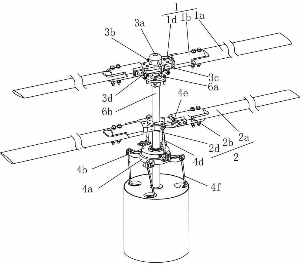
[0029] refer to figure 1 , the present embodiment provides a coaxial double-rotor aircraft with foldable blades, including an upper rotor assembly 1, a lower rotor assembly 2, an upper rotor pitch change mechanism 3, a lower rotor pitch change mechanism 4, a drive unit 5, a transmission mechanism and a power Unit 7 (power unit 7 in figure 1 not shown in the middle); the upper rotor assembly 1, the lower rotor assembly 2 and the power unit 7 are sequentially arranged from top to bottom, the drive unit 5 includes the upper rotor variable pitch drive 5a and the lower rotor variable pitch drive 5b, and the power unit 7 is used to simultaneously Drive the upper rotor assembly 1 and the lower rotor assembly 2 to rotate, the upper rotor pitch change drive 5a is used to realize the pitch change of the upper rotor assembly 1 through the upper rotor pitch change mechanism 3, and the lower rotor pitch change drive 5b is used to pass the lower rotor pitch change mechanism 4 Realize the 2...

Embodiment 2

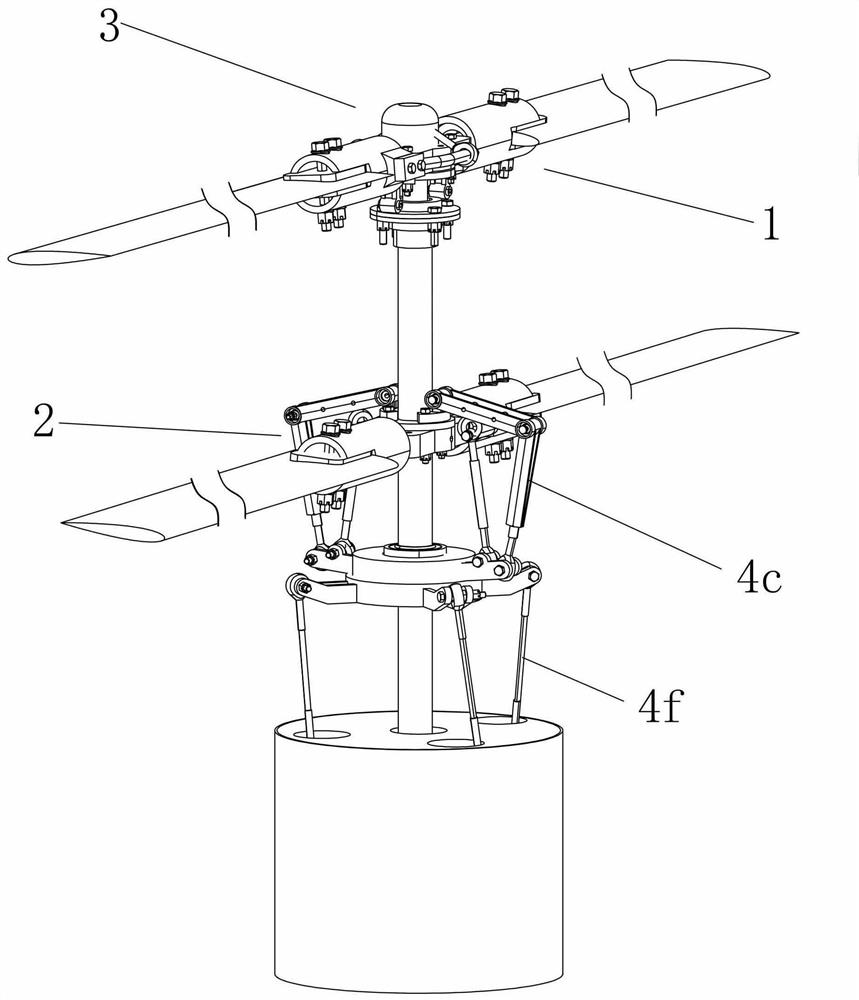
[0037] refer to figure 2 , and the difference from Embodiment 1 is that when the lower rotor assembly 2 is rotating, the lower propeller hub 2d will drive the lower rotating swash plate 4b to rotate through the lower pitch-changing rod 4d, and at this time, the lower pitch-changing rod 4d will be subjected to a greater force, In order to ensure the stability of the structure, the lower pitch-changing rod 4d has higher material requirements when selecting, so it is preferred that the lower rotor pitch-changing mechanism 4 also includes a lower synchronous rod assembly 4c, and the top of the lower synchronous rod assembly 4c is connected to the lower propeller hub 2d. The bottom end of the synchronous tie rod assembly 4c is movably connected with the lower rotating swash plate 4b, so that the lower rotor assembly 2 can drive the lower rotating swash plate 4b to rotate synchronously through the lower synchronous tie rod assembly 4c when rotating, so that the lower pitch-changing ...

Embodiment 3

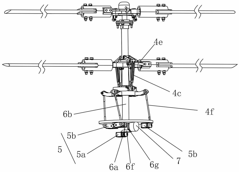
[0039] refer to image 3 , different from Embodiment 2, the power unit 7 can be selected as a motor. In order to realize that the power unit 7 simultaneously drives the upper rotor main shaft 6a and the lower rotor main shaft 6b and makes the upper rotor main shaft 6a and the lower rotor main shaft 6b rotate in opposite directions, at this time The transmission mechanism also includes the bevel teeth of the upper main shaft, the bevel teeth 6g of the torque relay and the bevel teeth 6f of the lower main shaft which are meshed in sequence; wherein, the bevel teeth of the upper main shaft are located directly above the bevel teeth 6f of the lower main shaft. At this time, the bevel teeth of the upper main shaft The umbrella-shaped teeth and the lower main shaft umbrella-shaped teeth 6f are arranged horizontally and oppositely, and the torque relay bevel-shaped teeth 6g are vertically arranged. Extend through the bevel teeth of the upper main shaft to connect with the bevel teeth...


PUM


Abstract

An upper rotor main shaft is sleeved with a lower rotor main shaft, a power unit is used for driving the upper rotor main shaft and the lower rotor main shaft to rotate, and an upper rotor variable-pitch driver, a lower rotor variable-pitch driver and the power unit are arranged below a lower rotor assembly. The upper rotor variable-pitch drive drives the upper rotor variable-pitch mechanism to achieve variable pitch of the upper rotor, the lower rotor variable-pitch drive drives the lower rotor variable-pitch mechanism to achieve variable pitch of the lower rotor assembly, the operating force of the double rotors is achieved, the same-speed rotation of the upper rotor and the lower rotor is achieved only through one power unit, the overall structure is simpler, and cost is lower. Meanwhile, the driving unit and the power unit are arranged below the lower-layer rotor wing assembly, so that the whole mass center of the unmanned aerial vehicle moves downwards, sufficient flight control force of the unmanned aerial vehicle in rolling and pitching motion is guaranteed, meanwhile, the system reliability is improved, maintenance of the driving unit and the power unit is more convenient, and the service life is prolonged.

Description

technical field [0001] The invention relates to the technical field of coaxial rotor unmanned aerial vehicles, in particular to a coaxial dual-rotor aircraft with foldable blades. Background technique [0002] Coaxial dual-rotor unmanned aerial vehicle refers to the aircraft with two upper and lower rotors that rotate forward and backward around the same vertical axis. Compared with traditional single-rotor unmanned helicopters, it does not need the tail rotor to change the course and balance torque, and only relies on the anti-torsion of the upper and lower rotors. The yaw control can be achieved by using the distance, and the coaxial dual-rotor UAV can also fold the blades, so the coaxial dual-rotor UAV has a smaller volume and higher energy utilization efficiency. [0003] At present, the rotor system of the existing coaxial dual-rotor unmanned aerial vehicle includes a single-layer periodic pitch-variable type and a double-layer periodic pitch-variable type. Although th...

Claims


Application Information

Patent Timeline
Patent Type & Authority Applications(China)
IPC IPC(8): B64C27/10B64C27/50B64C27/68
CPCB64C27/10B64C27/50B64C27/68
Inventor 王司令周洋吉思臣高嵩陈超波马天力赵素平王倩
Owner XIAN TECH UNIV
Why Eureka
Try Eureka