
Vortex reduction device, vortex reduction tube and method for arranging vortex reduction tube

A technology of vortex reducers and vortex tubes, which is applied in the field of setting vortex reducers, and can solve problems such as poor surface roughness, damage to vortex reducers, and shortening of the bleed air distance

Pending Publication Date: 2022-05-13
AECC COMML AIRCRAFT ENGINE CO LTD
View PDF0 Cites 0 Cited by
  • Summary
  • Abstract
  • Description
  • Claims
  • Application Information

AI Technical Summary

Problems solved by technology

[0003] In order to shorten the bleed air distance, the vortex reducer is generally a slender tubular structure with one end fixed. During operation, it is affected by the excitation of the engine rotor and the airflow excitation of the rotating disk cavity. Vibration problems are prone to occur in some working states of the engine, thereby damaging the vortex reducer. Tube
In order to alleviate the vibration problem of the vortex reducer, the traditional design uses a damping tube to reduce the risk of vibration, but the design of the damping tube is more complicated, and the slender and thin-walled damping tube is difficult to process, has low precision, poor surface roughness of the inner wall, and high processing costs
The inner wall of the damping tube is the flow channel for cooling the bleed air, and the poor surface roughness will reduce the bleed air efficiency
Similarly, the vortex reducer is also a slender tubular structure, and there are the same problems as the damper tube in processing

Method used


Image

  • Vortex reduction device, vortex reduction tube and method for arranging vortex reduction tube
  • Vortex reduction device, vortex reduction tube and method for arranging vortex reduction tube
  • Vortex reduction device, vortex reduction tube and method for arranging vortex reduction tube

Examples


Embodiment Construction

[0022] A variety of different implementations or examples for implementing the described subject technical solutions are disclosed below. In order to simplify the disclosure, the following describes the specific examples of each component and arrangement, of course, these are only examples, not limiting the protection scope of the present invention. For example, the description that the first feature described later in the description is formed on or above the second feature may include an embodiment in which the first and second features are formed through direct contact, and may also include an embodiment in which the first and second features are formed between the first and second features. Embodiments of additional features such that there may be no direct relationship between the first and second features. Additionally, reference numerals and / or letters may be repeated in different instances in these disclosures. This repetition is for brevity and clarity and does not i...


PUM


Abstract

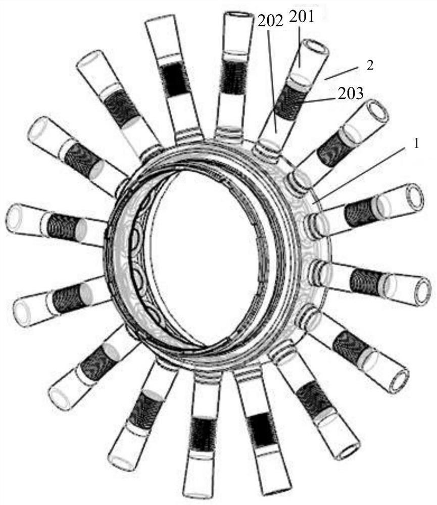
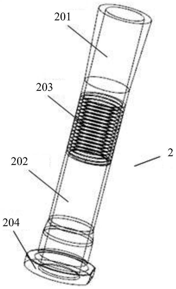
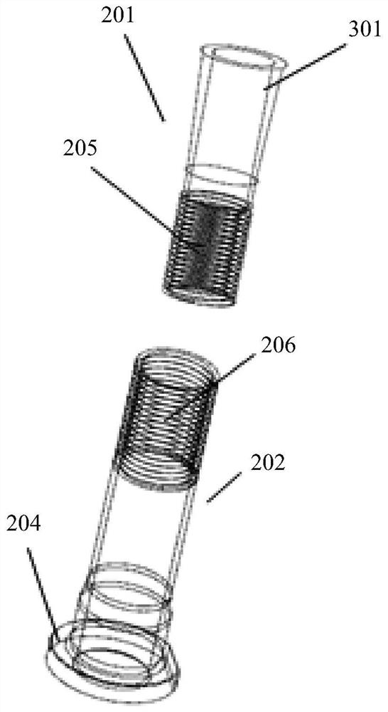
The invention provides a vortex reduction device, a vortex reduction tube and a method for arranging the vortex reduction tube. The vortex reduction tube comprises a base section and an extension section. Wherein the base section is provided with a base section first end and a base section second end, and the base section first end is used for being installed on a supporting ring of the vortex reduction device; the base section is provided with a first base section end and a second base section end, the extension section is provided with a first extension section end and a second extension section end, the second base section end and the first extension section end are in threaded connection in an anti-loose mode, and the second extension section end is arranged to be a free end of the vortex reduction pipe. The vibration resistance of the vortex reduction tube is improved.

Description

technical field [0001] The invention relates to a vortex reducer and a vortex reducer on a bleed air path in a high-pressure rotor of a gas turbine or an aeroengine, and a method for arranging the vortex reducer. Background technique [0002] In order to reduce the working temperature of parts such as turbine rotor blades and ensure the safety of the engine, it is necessary to introduce cooling gas from the high-pressure compressor to cool parts such as turbine rotor blades. In order to guide the air flow and reduce the flow loss of bleed air, a vortex reducer device is usually installed on the high-pressure compressor to improve the bleed air effect. [0003] In order to shorten the bleed air distance, the vortex reducer is generally a slender tubular structure with one end fixed. During operation, it is affected by the excitation of the engine rotor and the airflow excitation of the rotating disk cavity. In some working states of the engine, vibration problems are prone to...

Claims


Application Information

Patent Timeline
Patent Type & Authority Applications(China)
IPC IPC(8): F01D25/04F01D25/12F01D25/28F01D25/00
CPCF01D25/04F01D25/12F01D25/28F01D25/00
Inventor 张智轩张辉覃文源
Owner AECC COMML AIRCRAFT ENGINE CO LTD
Learn More