Stop valve capable of finely adjusting flow

A cut-off valve and flow rate technology, applied in the field of cut-off valves, can solve the problems of cut-off valves that cannot be fine-tuned and throttled stably, and achieve the effects of reducing flow rate, good fine-tuning control, and increasing the use effect

Pending Publication Date: 2022-05-13
JUHUA VALVE CO LTD
View PDF0 Cites 0 Cited by
  • Summary
  • Abstract
  • Description
  • Claims
  • Application Information

AI Technical Summary

Problems solved by technology

[0004] The purpose of the present invention is to provide a cut-off valve capable of fine-tuning the flow rate in order to solve the problem that the cut-off valve cannot be fine-tuned, making it unable to throttle stably.

Method used


Image

  • Stop valve capable of finely adjusting flow
  • Stop valve capable of finely adjusting flow
  • Stop valve capable of finely adjusting flow

Examples


Embodiment 1

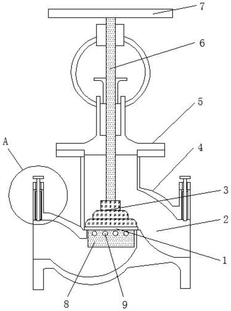
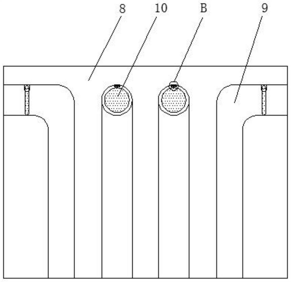
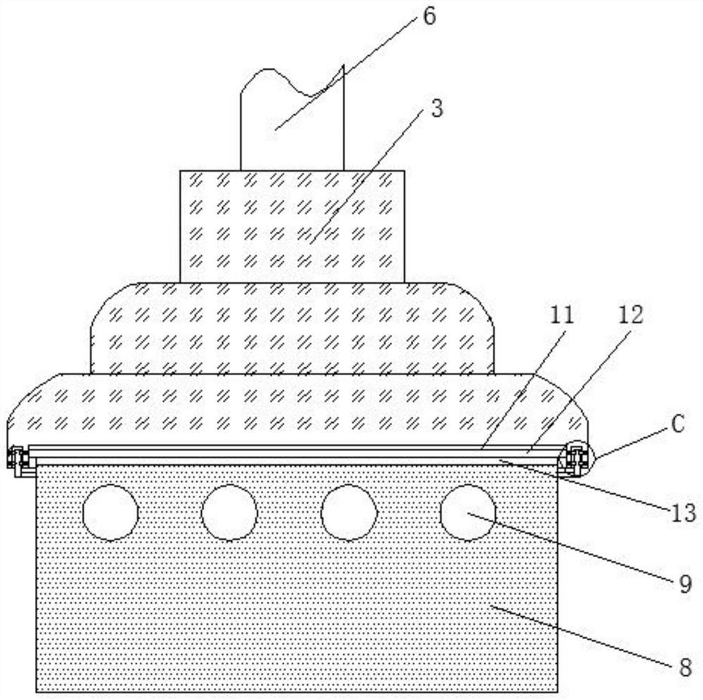
[0026] Embodiment one, with reference to figure 1 , 2 , 3 and 7: A cut-off valve capable of fine-tuning the flow rate, including a valve body 4, a valve hole 2 is opened inside the valve body 4, a valve cover 5 is fixed on the top of the valve body 4, and the inner surface wall of the valve hole 2 slides A valve stem 6 is embedded, and the top end of the valve stem 6 extends to the top of the valve cover 5, the top end of the valve stem 6 is provided with a hand wheel 7, the bottom of the valve stem 6 is provided with a valve disc 3, and the center of the valve hole 2 The top of the seat is fixed with a sealing seat cushion 1, and the top of the sealing seat cushion 1 is closely attached to the bottom edge of the valve disc 3, which is convenient for blocking the valve hole 2. There is a notch at the center of the bottom of the valve disc 3, and the notch The inner surface wall of the cylinder 8 is fixed with a first magnet layer 11, the bottom of the first magnet layer 11 is...

Embodiment 2

[0027] Embodiment two, refer to Figure 8: The bottom of the disc 3 is provided with four circular holes 25 equidistant along the circumferential direction, and the inner surface walls of the four circular holes 25 are all engaged with L-shaped rods 34, and the inner surface walls on both sides of the circular holes 25 are close to the center. Each side is provided with a square mouth 28, and the inner surface walls on both sides of the square mouth 28 are provided with chute 27 along the horizontal direction. There are sliders 32, and the sliders 32 slide left and right on the inner surface wall of the chute 27. There are multiple sliders 32, and they are divided into multiple groups. A fixed plate 31 is welded between each group of two sliders 32. One side outer surface center of fixed plate 31 is welded with compression spring 30, and one end of compression spring 30 is welded with the inner surface wall of square mouth 28, and the outer surface of compression spring 30 is ...

Embodiment 3

[0028] Embodiment three, refer to Figure 4 , 5 And 6: the top of the valve body 4 is welded with a fixed block 35 near the edges of both sides, the fixed block 35 is provided with a threaded hole 36 along the vertical direction, the inner surface wall of the threaded hole 36 is threadedly connected with a screw rod 14, and the screw rod 14 extends to the outside of the fixed block 35, and the screw rod 14 can be moved up and down by rotating the screw rod 14 on the inner surface wall of the threaded hole 36. The inside of the valve body 4 is located at the bottom of the fixed block 35 and opened vertically. There is a receiving hole 37, the top of the receiving hole 37 communicates with the bottom of the threaded hole 36, the outer surfaces of both sides of the screw mandrel 14 are welded with U-shaped long blocks 15, and the inner surface walls of both sides of the U-shaped long block 15 are along the vertical direction. Two rotating rods 17 are welded, the outer surface of...


PUM


Abstract

The stop valve comprises a valve body, a valve hole is formed in the valve body, a valve deck is fixed to the top of the valve body, a valve rod is slidably embedded in the inner surface wall of the valve hole, the top end of the valve rod extends to the top of the valve deck, the top end of the valve rod is sleeved with a hand wheel, and the bottom of the valve rod is sleeved with a valve clack. A sealing seat cushion is fixed to the top of the center of the valve hole, and the top of the sealing seat cushion is tightly attached to the edge of the bottom of the valve clack. According to the device, an L-shaped water hole is completely leaked out, then the flow of liquid is increased, the liquid flows in the L-shaped water hole, so that a circular plate rotates, the liquid can flow better, water is partially blocked through the circular plate, and the flow of the liquid can be finely adjusted better; therefore, the usability of the stop valve can be better improved, and fine adjustment throttling can be better achieved.

Description

technical field [0001] The invention belongs to the technical field of cut-off valves, in particular to a cut-off valve capable of fine-tuning flow. Background technique [0002] Globe valve, also known as cut-off valve, is a forced sealing valve. Therefore, when the valve is closed, pressure must be applied to the disc to force the sealing surface not to leak. The most widely used valve on the market is the globe valve. The existing globe valves are The flow of liquid is realized by controlling the opening and closing of the valve disc. [0003] However, in the prior art, when the stop valve is used, the flow of the stop valve is only controlled by a single disc, and when some precise flow is fine-tuned and controlled, it cannot be realized, which will greatly reduce the flow rate of the stop valve. Reduce the usability of the cut-off valve so that it cannot be better controlled in a small range. At the same time, the existing cut-off valve has no obvious throttling effect...

Claims


Application Information

Patent Timeline
Patent Type & Authority Applications(China)
IPC IPC(8): F16K1/02F16K1/32F16K1/36F16K1/46F16K1/52F16K27/02F16K31/60F16K3/08F16K3/314F16K3/30F16K27/04F16K31/50
CPCF16K1/02F16K1/32F16K1/36F16K1/46F16K1/52F16K27/0218F16K27/02F16K31/60F16K3/085F16K3/029F16K3/314F16K3/30F16K27/045F16K31/50
Inventor 胡汗华
Owner JUHUA VALVE CO LTD
Why Eureka
Try Eureka