Pilot diaphragm type pressure reducing valve with adjustable pressure

A pressure reducing valve and diaphragm type technology, which is applied in the field of pressure reducing valves, can solve problems such as attenuation of outflow pressure adjustment accuracy, expansion of inlet and outlet pressure differences, etc.

Active Publication Date: 2022-05-13
艾肯(江苏)工业技术有限公司
View PDF14 Cites 0 Cited by
  • Summary
  • Abstract
  • Description
  • Claims
  • Application Information

AI Technical Summary

Problems solved by technology

[0004] The current pilot-operated pressure reducing valve generally judges the pressure fluctuation of the inlet water flow through the pressure difference between the inlet and outlet. In a stable state, if the inlet pressure increases, the overcurrent flow will increase slightly, and the outlet pressure will also increase. However, the increase of the outlet pressure will not be as high as the increase of the inlet pressure, and the pressure difference between the inlet and outlet will expand. At this time, adjust the cross-section size of the pressure reducing valve to increase the flow resistance, so that the inlet pressure will experience a greater pressure drop. Outflow pressure, it is expected that the outflow pressure will return to the initial value, but this adjustment process cannot accurately know whether the outflow pressure returns to the initial value, it can only make the outflow pressure return to a state point slightly deviated from the initial value, the valve is in During manufacture, the adjustment ratio of the overflow opening is adjusted according to the design flow rate, which can obtain greater pressure reduction adjustment accuracy under the design flow rate. attenuation

Method used


Image

  • Pilot diaphragm type pressure reducing valve with adjustable pressure
  • Pilot diaphragm type pressure reducing valve with adjustable pressure
  • Pilot diaphragm type pressure reducing valve with adjustable pressure

Examples


Embodiment Construction

[0037] The following will clearly and completely describe the technical solutions in the embodiments of the present invention with reference to the accompanying drawings in the embodiments of the present invention. Obviously, the described embodiments are only some, not all, embodiments of the present invention. Based on the embodiments of the present invention, all other embodiments obtained by persons of ordinary skill in the art without making creative efforts belong to the protection scope of the present invention.

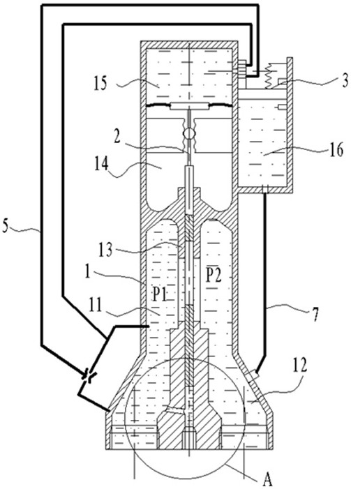
[0038] see Figure 1-Figure 5 , the present invention provides technical solutions:

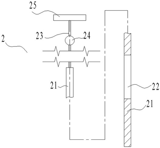
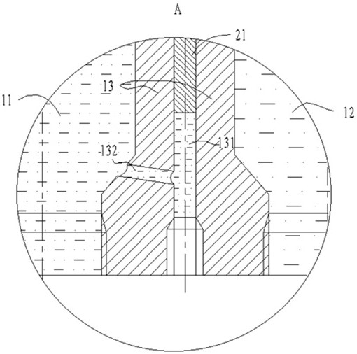
[0039] A pressure-adjustable pilot diaphragm pressure reducing valve. The pressure reducing valve includes a valve housing 1, a shut-off assembly 2, and a diaphragm 4. The valve housing 1 includes an inner symmetrically distributed inlet flow channel 11, an outlet flow channel 12 and two A partition 13 separated by two flow passages, a transition chamber 14 and a balance cha...


PUM


Abstract

The invention relates to the technical field of pressure reducing valves, in particular to a pressure-adjustable pilot diaphragm type pressure reducing valve which comprises a valve shell, a cut-off assembly and a diaphragm, the valve shell comprises an inlet runner, an outlet runner and a partition plate, the inlet runner and the outlet runner are symmetrically distributed in the valve shell, the partition plate separates the two runners, a transition cavity and a balance cavity are further formed in the valve shell, and the transition cavity is located in the middle of the valve shell; an overflow hole is formed in the middle of the partition plate, a flashboard groove is formed in the wall thickness of the partition plate, one end of the closure assembly is located in the flashboard groove, the other end of the closure assembly penetrates through the transition cavity, the end of the closure assembly is connected with a diaphragm, and the outer edge of the diaphragm is connected to the inner wall of the valve shell. The transition cavity and the balance cavity are jointly separated by the diaphragm and the end of the closure assembly, the closure assembly controls the overflowing area of the overflowing hole to adjust the overflowing resistance of the inflow channel and the outflow channel, a pressure guiding hole is formed between the side face of the end, away from the transition cavity, of the flashboard groove and the inflow channel, and the balance cavity is filled with a pressure reducing valve overflowing medium. And the pressure of the runner is accurately kept at a design value.

Description

technical field [0001] The invention relates to the technical field of pressure reducing valves, in particular to a pressure-adjustable pilot diaphragm type pressure reducing valve. Background technique [0002] The pressure reducing valve is a variety of valves, and its main function is to maintain the outlet pressure of the valve at a stable value. [0003] According to the structure, the current pressure reducing valve can be roughly divided into film type, lever type, piston type, bellows type, etc., and can be divided into spring direct acting type and pilot differential pressure type according to the working principle. Among them, the pilot pressure reducing valve can be used as Smaller sizes are widely used for narrower pressure fluctuations. [0004] The current pilot-operated pressure reducing valve generally judges the pressure fluctuation of the inlet water flow through the pressure difference between the inlet and outlet. In a stable state, if the inlet pressure...

Claims


Application Information

Patent Timeline
Patent Type & Authority Applications(China)
IPC IPC(8): F16K17/22F16K27/04
CPCF16K17/22F16K27/044
Inventor 仇鑫凯张正凯姜宏明赵俊
Owner 艾肯(江苏)工业技术有限公司
Why Eureka
Try Eureka