Integrated device of navigation light and navigation antenna

A technology of integrated devices and navigation lights, applied in lighting devices, lighting devices, fixed lighting devices, etc., can solve the problem that internal electronic components cannot withstand extremely low temperature electrical characteristics for a long time, navigation antennas have low heat generation, and cannot meet the use requirements, etc. problem, to achieve the effect of simple structure, strong adaptability and versatility, and fast speed

Pending Publication Date: 2022-05-13
CHINA ACAD OF AEROSPACE AERODYNAMICS
View PDF0 Cites 0 Cited by
  • Summary
  • Abstract
  • Description
  • Claims
  • Application Information

AI Technical Summary

Problems solved by technology

The navigation lights will generate a lot of heat during the power-on process, and the heat will not be effectively used and directly lost in the air
However, the navigation antenna itself generates very little heat. When working in an extremely low temperature environment, its electrical characteristics are seriously affected due to its low noise level or the internal electronic components cannot withstand the extremely low temperature for a long time, resulting in performance degradation or functional failure. To meet the requirements of extremely low temperature conditions, additional environmental control design is required
Generally, environmental control designs increase the internal temperature of the navigation antenna by means of electric heating plates, or separate low-noise amplifiers or electronic components that cannot withstand extremely low temperature environments from the interior of the navigation antenna for separate insulation and heating, which requires additional power consumption or other heat energy. , which also increases the weight of airborne equipment

Method used


Image

  • Integrated device of navigation light and navigation antenna
  • Integrated device of navigation light and navigation antenna
  • Integrated device of navigation light and navigation antenna

Examples


Embodiment

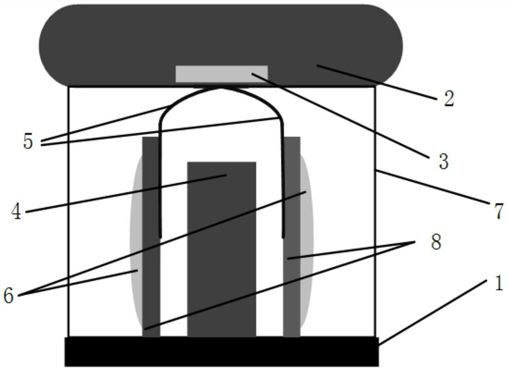
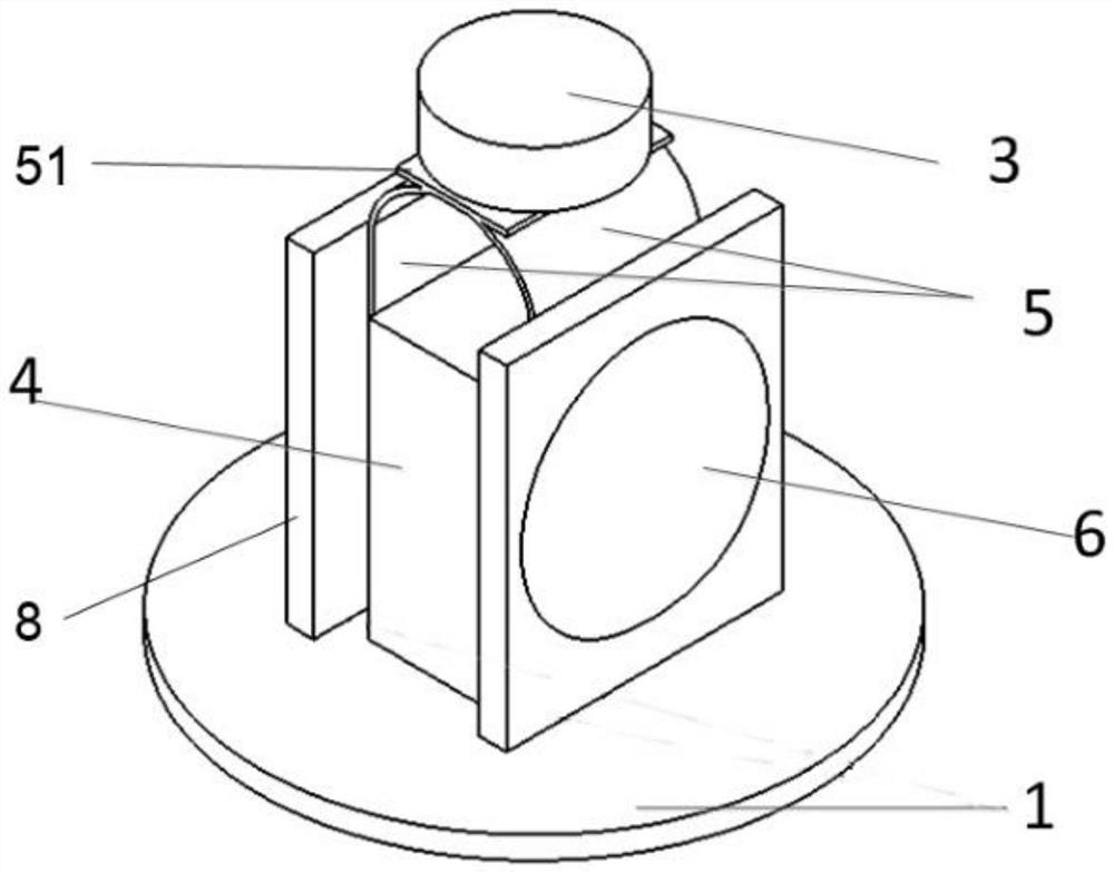
[0058] refer to Figure 1-Figure 4 As shown, this embodiment provides an integrated device for navigation lights and navigation antennas, including:

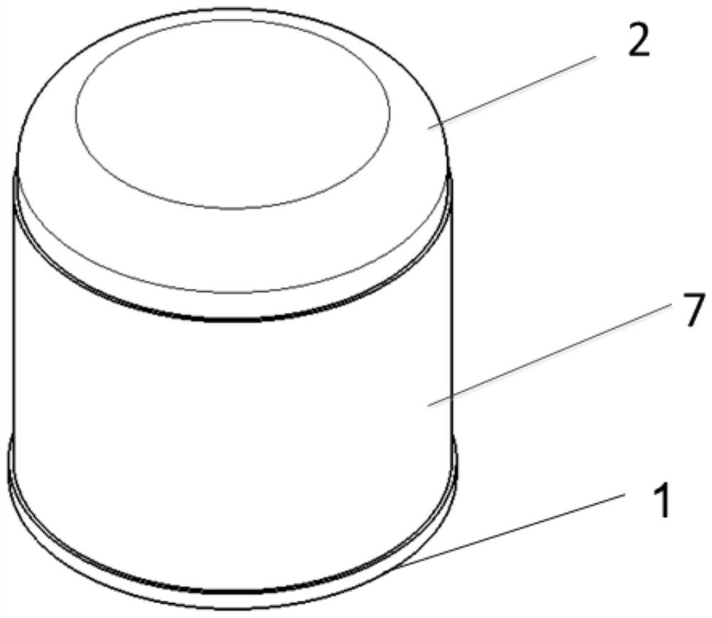
[0059] outer cover 7;

[0060] Navigation light, the navigation light is arranged in the outer cover;

[0061] Navigation antenna 2, the navigation antenna 2 is connected with the outer cover 7;

[0062] The heat conduction element 5 is arranged in the outer cover 7 , one end of the heat conduction element 5 is connected to the back heating area 602 of the navigation light, and the other end of the heat conduction element 5 is connected to the navigation antenna 2 .

[0063] In this embodiment, the navigation light includes a navigation light controller 4, a base 1 and a plurality of light sources 6, the base 1 is connected with the outer cover 7 to form an accommodation cavity, the navigation light and a plurality of light sources 6 are arranged in the accommodation cavity, and the navigation light control The device 4 is co...


PUM


Abstract

The invention provides an integrated device of a navigation light and a navigation antenna. The integrated device comprises an outer cover; the navigation light is arranged in the outer cover; the navigation antenna is connected with the outer cover; one end of the heat conduction piece is connected with a back heating area of the navigation lamp, and the other end of the heat conduction piece is connected with the navigation antenna. The technical scheme has the beneficial effects that the navigation lamp and the navigation antenna are integrated, the navigation antenna can borrow heat emitted by the navigation lamp, the heat conduction piece made of the high-heat-conduction material is adopted, heat generated by the lamp source can be rapidly conducted to the bottom of the navigation antenna, then the internal temperature of the navigation antenna is increased, and the navigation effect is improved. And normal work under the extremely low-temperature working condition can be ensured. And the phenomenon that the internal temperature of the navigation antenna is too low under an extremely low temperature working condition to influence the electrical characteristics is effectively avoided. The system has the advantages of low-temperature working condition resistance and high integration level.

Description

technical field [0001] The invention belongs to the technical field of integrated electronic equipment, and more specifically relates to an integrated device of a navigation light and a navigation antenna. Background technique [0002] Navigation antennas and navigation lights installed on aircraft and ships are generally exposed to the outside for use. Navigation lights will generate a lot of heat in the process of electrification, which is not effectively used and directly lost in the air. However, the navigation antenna itself generates very little heat. When working in an extremely low temperature environment, its electrical characteristics are seriously affected due to its low noise level or the internal electronic components cannot withstand the extremely low temperature for a long time, resulting in performance degradation or functional failure. To meet the use requirements of extremely low temperature conditions, additional environmental control design is required. ...

Claims


Application Information

Patent Timeline
IPC IPC(8): F21S8/00F21V29/70F21V29/503F21V33/00H01Q1/28H01Q1/34H01Q1/02F21Y115/10F21W107/20
CPCF21S8/00F21V29/70F21V29/503F21V33/00H01Q1/28H01Q1/34H01Q1/02F21W2107/20F21Y2115/10
Inventor 兰根龙俱子研任素萍栾金谕郭林贾浩哲
Owner CHINA ACAD OF AEROSPACE AERODYNAMICS
Why Eureka
Try Eureka