Drainage waste heat utilization system of power station boiler

A power plant boiler and water-repellent technology, which is applied in the direction of boiler cleaning equipment, etc., can solve the problems of energy waste and ineffective utilization of calorific value, and achieve the effect of improving the effect of waste heat utilization

Pending Publication Date: 2022-05-13
温州宏泽热电股份有限公司
View PDF0 Cites 0 Cited by
  • Summary
  • Abstract
  • Description
  • Claims
  • Application Information

AI Technical Summary

Problems solved by technology

[0006] In view of the above-mentioned related technologies, the inventor believes that there are the following defects: the water generated by the boiler steam generally has a relatively high temperature and pressure, so it has a high heat enthalpy value, and the natural cooling of the water after entering the water tank leads to its heat loss. value cannot be effectively utilized, resulting in energy waste

Method used


Image

  • Drainage waste heat utilization system of power station boiler
  • Drainage waste heat utilization system of power station boiler
  • Drainage waste heat utilization system of power station boiler

Examples


Embodiment Construction

[0041] The following is attached Figure 1-5 The application is described in further detail.

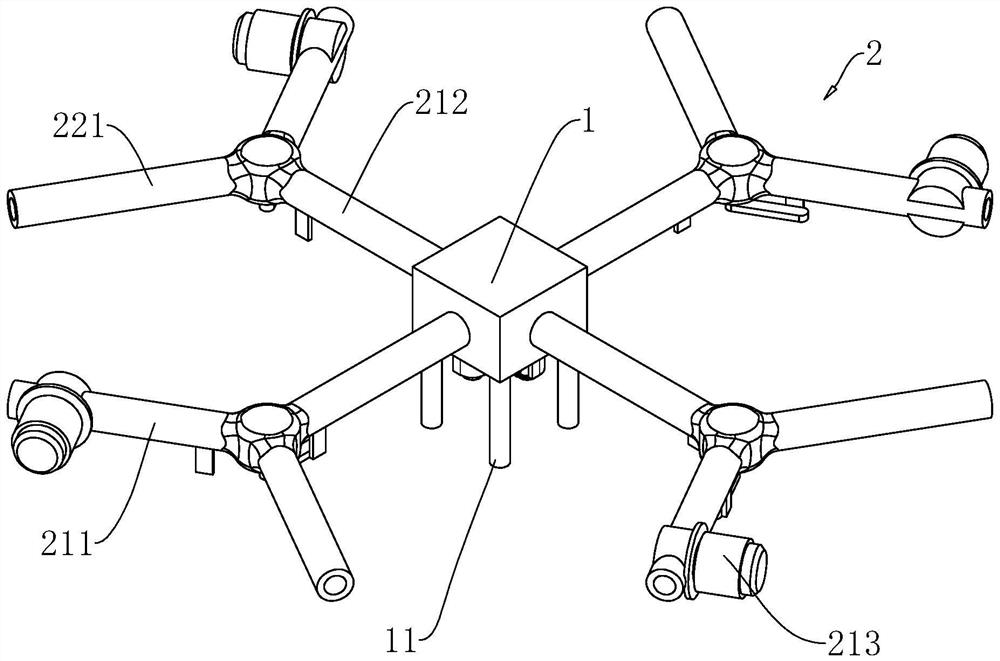
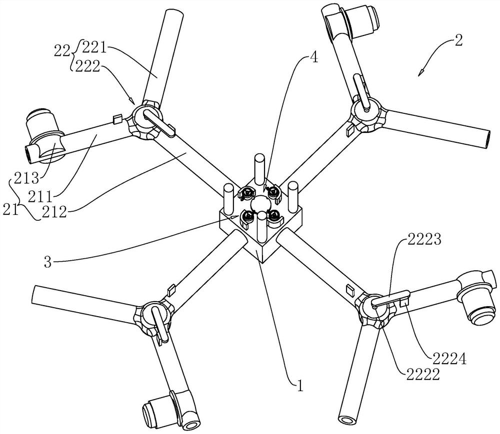
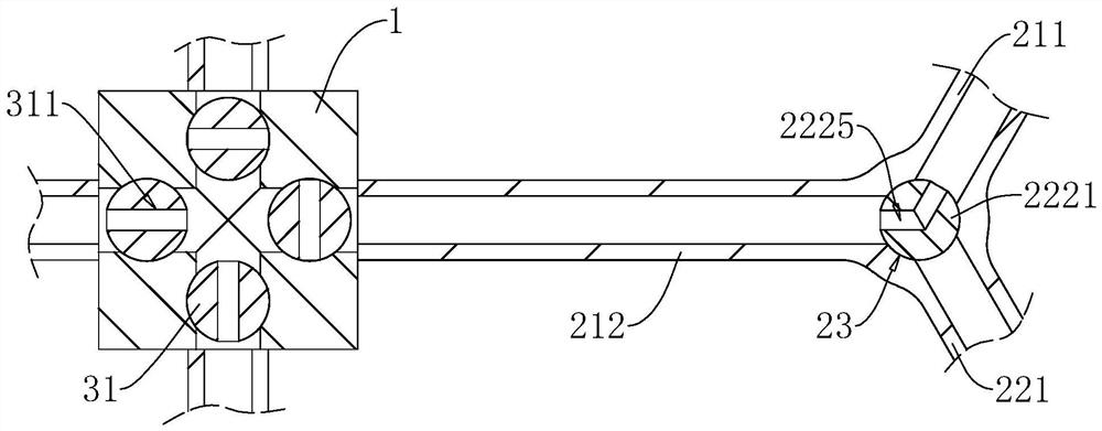
[0042] The embodiment of the present application discloses a drainage waste heat utilization system of a utility boiler. refer to figure 1 , figure 2 , The drainage waste heat utilization system of the power plant boiler includes a water collection tank 1, four sets of water outlet and return devices 2, four sets of opening and closing mechanisms 3 and a locking mechanism 4, and four support columns 11 are fixed on the bottom wall of the water collection tank 1.

[0043] refer to figure 2 , image 3 The water outlet and return device 2 includes a water outlet mechanism 21 and a water return mechanism 22 , the water outlet mechanism 21 includes a water outlet pipe 211 , a water collection pipe 212 and a drain pump 213 , and the water return mechanism 22 includes a water inlet pipe 221 and a water blocking assembly 222 . One end of the water outlet pipe 211 is used to be fixed o...


PUM


Abstract

The drainage waste heat utilization system of the power station boiler comprises a water collecting tank and multiple sets of water outlet and return devices, each water outlet and return device comprises a water outlet mechanism and a water return mechanism, the water outlet mechanism comprises a water outlet mechanism arranged on a drainage tank, and the water return mechanism comprises a water inlet pipe connected to a water cooling wall. The water outlet mechanism and the water collecting tank are used for inputting drained water into the water inlet pipe of the other water outlet and return device. The method has the effect of improving the drainage waste heat utilization effect.

Description

technical field [0001] The present application relates to the field of waste heat utilization, in particular to a drainage waste heat utilization system for power plant boilers. Background technique [0002] Power plant boilers are mainly divided into pulverized coal boilers and circulating fluidized bed boilers. The circulating fluidized bed boilers use the clean coal combustion technology with the highest degree of industrialization. [0003] The boiler includes a furnace, a cold water wall installed in the furnace, a steam drum connected to the cold water wall, a downcomer connecting the steam drum and the cold water wall, and a steam pipe connected to the steam drum. The water in the tank is heated so that the water in the cold water wall forms a steam-water mixture and enters the steam drum. After the steam-water mixture is separated by the steam drum, the water returns to the cold water wall through the downcomer, and the water vapor is transported to the steam turbine...

Claims


Application Information

Patent Timeline
Patent Type & Authority Applications(China)
IPC IPC(8): F22B37/50
CPCF22B37/50
Inventor 卢石凡曾云怡张洪学李小波宋绍
Owner 温州宏泽热电股份有限公司
Why Eureka
Try Eureka