Photoelectric device test conversion clamp

A technology for optoelectronic devices and fixtures, which is applied in the parts, instruments, and measuring devices of electrical measuring instruments. Strong overcurrent protection capability and the effect of improving test yield

Pending Publication Date: 2022-05-13
CHINA ACADEMY OF SPACE TECHNOLOGY
View PDF0 Cites 1 Cited by
  • Summary
  • Abstract
  • Description
  • Claims
  • Application Information

AI Technical Summary

Problems solved by technology

[0003] With the development needs of spacecraft, there are often quality assurance tasks for optoelectronic special packaged devices, such as PILL packaged optoelectronic devices, which are currently tested by developing external adapters on special equipment. In the process of testing such special packaged devices There are three major difficulties: (1) Due to the small size of the device package (about 2mm in length and about 1.50mm in diameter at the bottom), the lead-out end of the device is only 0.41mm, so it is difficult to control the contact of the general adapter, resulting in poor test contact. Poor test accuracy; (2) The size of the device is small, and the process of testing and clamping the device is likely to cause mechanical damage to the device; (3) Due to the existence of processing errors, the traditional adapter fixation method has a device position offset, and the device cannot be accurately positioned in the adapter

Method used


Image

  • Photoelectric device test conversion clamp
  • Photoelectric device test conversion clamp
  • Photoelectric device test conversion clamp

Examples


Embodiment Construction

[0031] The following describes the present invention in detail, and the features and advantages of the present invention will become more clear and definite along with these descriptions.

[0032] The word "exemplary" is used exclusively herein to mean "serving as an example, embodiment, or illustration." Any embodiment described herein as "exemplary" is not necessarily to be construed as superior or better than other embodiments. While various aspects of the embodiments are shown in drawings, the drawings are not necessarily drawn to scale unless specifically indicated.

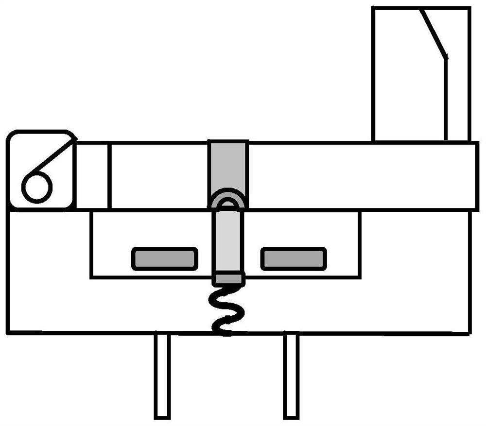
[0033] Aiming at the problems existing in the existing test fixtures, the invention designs a test conversion fixture for PILL packaged photoelectric devices, solves the test requirements of PILL packaged photoelectric devices, and greatly improves the efficiency.

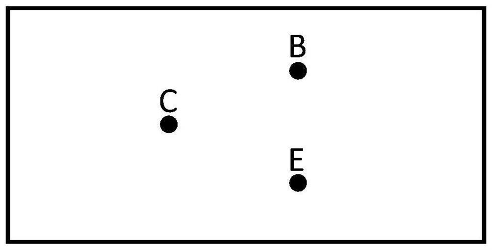
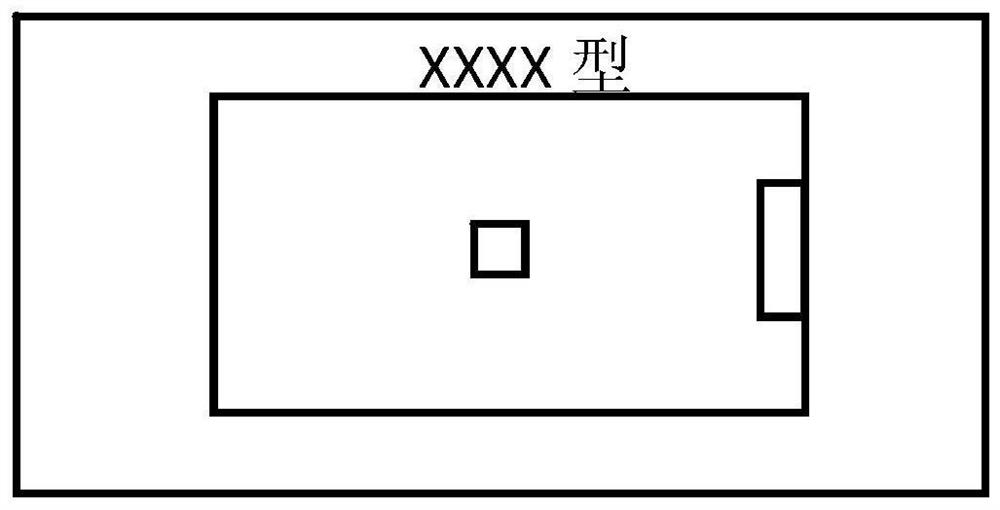
[0034] The structure of the photoelectric device test conversion fixture of the present invention is as follows: figure 1 , figure 2 , ima...


PUM


Abstract

The invention discloses a test conversion clamp for a photoelectric device. The test conversion clamp comprises clamp pins, a lower bottom plate, a middle interface plate, a spring piece and an upper cover plate, the middle interface plate is fixedly installed on the lower bottom plate, the middle interface plate is provided with a groove used for installing a device to be tested, the spring piece is fixed at the bottom of the groove, one end of the clamp pin is connected with the spring piece, and the other end of the clamp pin extends to the outside of the lower bottom plate; one end of the upper cover plate is rotatably connected with the middle interface plate, a to-be-tested device is arranged in a groove formed in the middle interface plate, the upper cover plate presses the to-be-tested device, meanwhile, the leading-out end of the to-be-tested device presses the spring piece, the to-be-tested device is connected with the clamp pin through the spring piece, and the cover plate is provided with a light window corresponding to the to-be-tested device. Light emitted by the light source reaches the to-be-tested device through the light window. The switching clamp is simple in structure, rapid to install, convenient to disassemble, wide in applicability, capable of effectively improving the testing efficiency, high in stability and capable of effectively improving the testing yield.

Description

technical field [0001] The invention belongs to the technical field of photoelectric device testing, and in particular relates to a photoelectric device testing conversion fixture. Background technique [0002] The electrical performance test of components is an essential and important test content for the screening test and reliability test of aerospace components. Due to the special performance of optoelectronic devices, there are not only tests in the electrical field but also tests in the optical field. The implementation method mostly adopts special photoelectric test equipment. Special equipment has limitations in the testing of optoelectronic special packaging devices. [0003] With the development needs of spacecraft, there are often quality assurance tasks for optoelectronic special packaged devices, such as PILL packaged optoelectronic devices, which are currently tested by developing external adapters on special equipment. In the process of testing such special p...

Claims


Application Information

Patent Timeline
Patent Type & Authority Applications(China)
IPC IPC(8): G01R1/04
CPCG01R1/0425
Inventor 李庆庄仲杨发明王雪生于福莉赵亚娟景福冈董浩威王锦
Owner CHINA ACADEMY OF SPACE TECHNOLOGY
Why Eureka
Try Eureka