
Radar radio frequency front end and speed measuring radar

A radio frequency front-end and radar technology, which is applied in the direction of measuring devices, using re-radiation, radio wave measurement systems, etc., can solve the problems of complex test schemes, high test costs, and low test efficiency

Pending Publication Date: 2022-05-13
BEIJING CHANGFENG BROADCASTING COMM EQUIP
View PDF0 Cites 0 Cited by
  • Summary
  • Abstract
  • Description
  • Claims
  • Application Information

AI Technical Summary

Problems solved by technology

[0004] Existing testing schemes are relatively complex and need to rely on external testing equipment, resulting in low testing efficiency and high testing costs

Method used


Image

  • Radar radio frequency front end and speed measuring radar
  • Radar radio frequency front end and speed measuring radar
  • Radar radio frequency front end and speed measuring radar

Examples


Embodiment Construction

[0033] The technical solutions of the present invention will be further described below in conjunction with the accompanying drawings and through specific implementation methods. It should be understood that the specific embodiments described here are only used to explain the present invention, but not to limit the present invention. In addition, it should be noted that, for the convenience of description, only some structures related to the present invention are shown in the drawings but not all structures.

[0034] Before discussing the exemplary embodiments in more detail, it should be mentioned that some exemplary embodiments are described as processes or methods depicted as flowcharts. Although the flowcharts describe the steps as sequential processing, many of the steps may be performed in parallel, concurrently, or simultaneously. Additionally, the order of steps may be rearranged. The process may be terminated when its operations are complete, but may also have addit...


PUM


Abstract

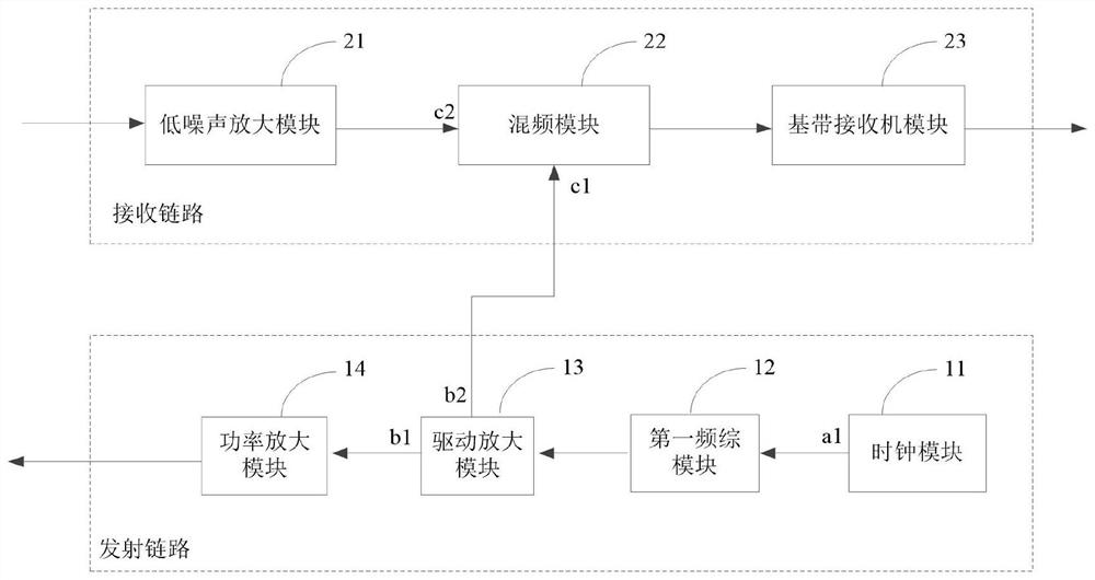
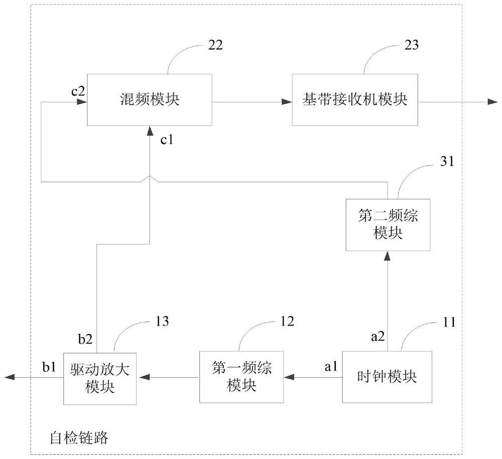
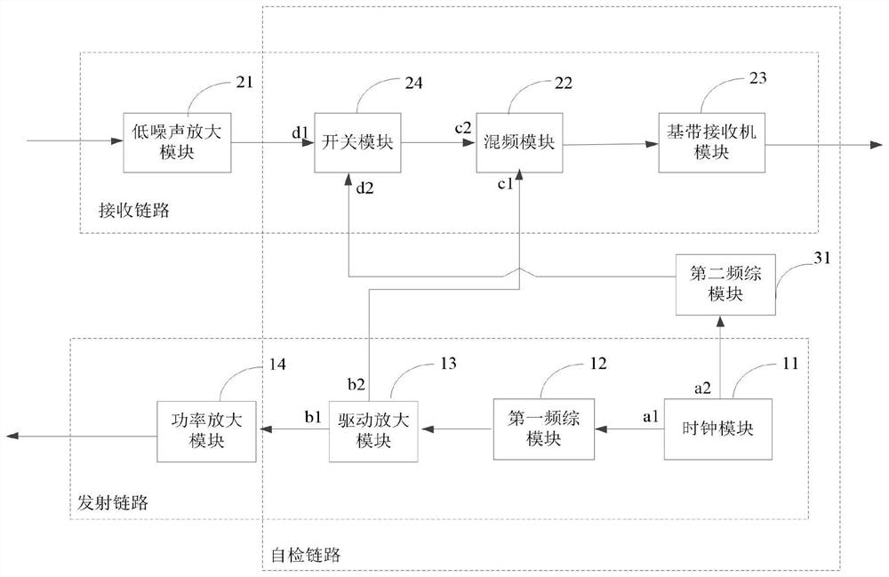
The embodiment of the invention discloses a radar radio frequency front end and a speed measuring radar. A self-checking link is formed by a second frequency synthesizer module, a clock module, a first frequency synthesizer module, a driving amplification module, a frequency mixing module and a baseband receiver module of the radar radio frequency front end; and the self-checking link is used for carrying out self-checking on the radar radio frequency front end when the radar works in the self-checking mode. According to the self-checking mode, a first continuous wave signal and a second continuous wave signal which are different in frequency are generated through the first frequency synthesizer module and the second radio frequency module so that simulation of Doppler frequency offset of a moving target object can be achieved, self-checking of hardware contained in the radar radio frequency front end can be achieved, and when the target speed is consistent with the preset speed, self-checking of the hardware contained in the radar radio frequency front end can be achieved. The radar radio frequency front end and the speed measuring radar provided by the embodiment of the invention can achieve the technical effect of quick self-inspection when the self-inspection of the radar radio frequency front end is passed, and compared with the prior art, the radar radio frequency front end and the speed measuring radar do not need to depend on external test equipment, and the test cost is relatively low.

Description

technical field [0001] The embodiment of the present invention relates to the field of computer microwave technology, in particular to a radar radio frequency front end and a speed measuring radar. Background technique [0002] The speed measuring radar uses the Doppler frequency shift caused by the moving target to detect the speed of the target object by shifting the frequency difference. The speed measuring radar has been widely used in military and civilian use. Among them, the RF front-end is an important part of the speed radar. The RF front-end mainly completes the functions of signal generation, transmission, reception, amplification, and down-conversion, which plays a decisive role in the performance of the entire radar system. [0003] Due to the large amount of hardware contained in the RF front-end, in order to avoid the failure of the measurement task due to hardware failures in the RF front-end during installation, commissioning and use of the speed measuring r...

Claims


Application Information

Patent Timeline
Patent Type & Authority Applications(China)
IPC IPC(8): G01S13/58G01S7/02
CPCG01S13/58G01S7/02
Inventor 吴成才王志宇赵军司谪仙侯玉林杨颖赵晋娟蒋全
Owner BEIJING CHANGFENG BROADCASTING COMM EQUIP
Learn More