Floating type plug-in computer equipment
A computer equipment, floating technology, applied in the field of floating plug-in computer equipment, can solve the problems of slow system running speed, poor heat dissipation of main equipment, easy burning of parts, etc., to achieve the effect of accelerating heat dissipation
- Summary
- Abstract
- Description
- Claims
- Application Information
AI Technical Summary
Problems solved by technology
Method used
Image

Examples
Embodiment 1
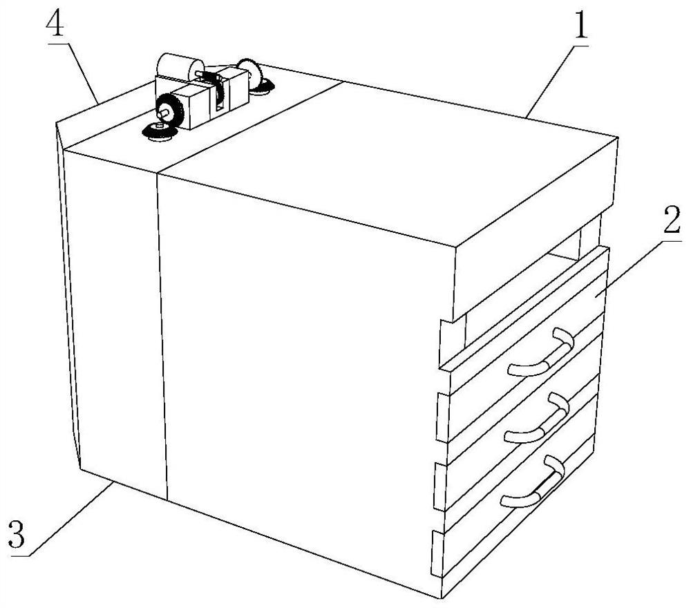
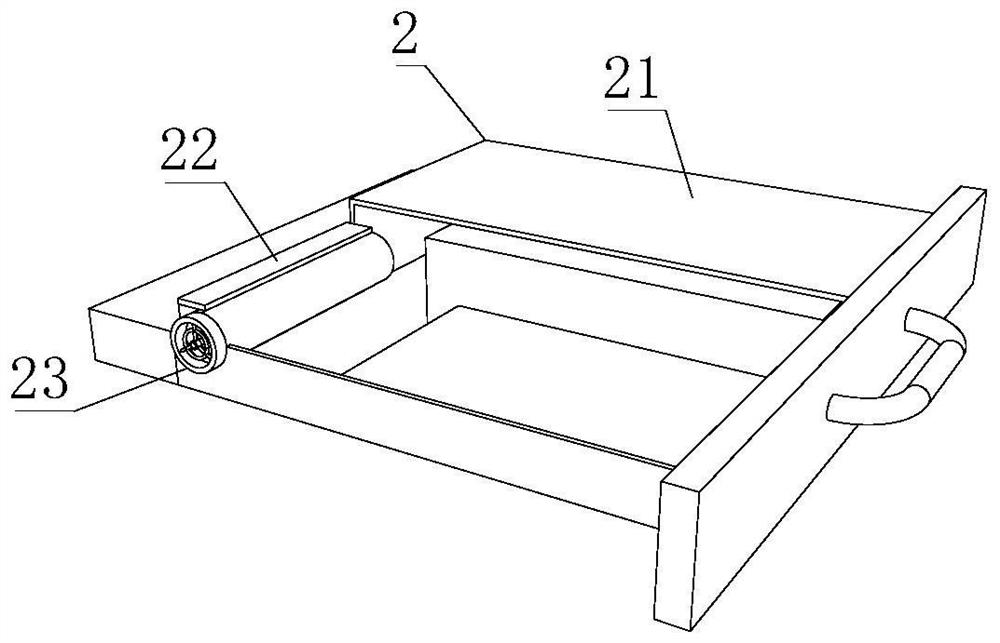
[0034] Such as Figure 1-7 As shown, the present invention provides a floating plug-in computer device, including a plug-in computer device body 2, the plug-in computer device body 2 includes a plug-in computer device shell 21, and the inside of the plug-in computer device shell 21 is fixedly connected with a fixed The plate 22, the inside of the fixed plate 22 is fixedly connected with a dust removal and heat dissipation cylinder mechanism 23, the dust removal and heat dissipation cylinder mechanism 23 includes a spiral vane mechanism 233, and the spiral vane mechanism 233 includes a spiral dust suction column 2333, and the outer side of the computer equipment body 2 is movable. The plug-in base 1 is connected, and the rear side of the plug-in base 1 is fixedly equipped with a heat dissipation cover mechanism 3. The heat dissipation cover mechanism 3 includes an arc fan wheel 37 and a right fan wheel mechanism 310, and one side of the arc fan wheel 37 is fixed. A fan rim 314 ...
Embodiment 2
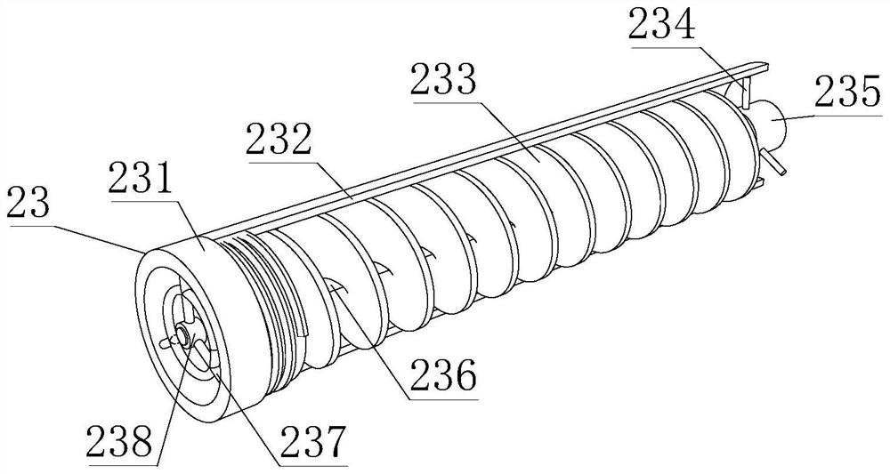
[0037] Such as Figure 1-7 As shown, on the basis of Embodiment 1, the present invention provides a technical solution: preferably, the outer side of the spiral dust suction column 2333 is fixedly connected with the base frame plate 2335, and the right side of the spiral dust suction column 2333 is fixedly connected with a partition ring 2332, the interior of the partition ring 2332 is fixedly connected with a dust suction ball 2334, one side of the partition ring 2332 is fixedly connected with one side of the base frame plate 2335, and the other side of the base frame plate 2335 is fixedly connected with a dust suction plate 2331.
[0038] In this embodiment, the spiral blade mechanism 233 is used to rotate and push the air, and the internal dust is carried out together. When it comes into contact with the dust collection plate 2331, a large area of adsorption is carried out. The two basic frame plates 2335 increase the carrier area, and then Increase the adsorption area, the...
Embodiment 3
[0040] Such as Figure 1-7 As shown, on the basis of Embodiment 1, the present invention provides a technical solution: preferably, the central shaft 236 is fixedly connected to the middle of the spiral blade mechanism 233, and a positioning cover 2311 is arranged outside the central shaft 236, and the positioning cover 2311 The right side of the connecting shaft sleeve 2310 is fixedly connected with a connecting shaft sleeve 2310, and the inner wall of the connecting shaft sleeve 2310 is clamped with a square connecting column 239. The right side of the square connecting column 239 is fixedly connected with a servo motor 235, and the outer side of the servo motor 235 is fixedly connected with a fixed Rod one 234, the outer side of the fixed rod one 234 is fixedly connected with a cylindrical casing 232, the inner wall of the cylindrical casing 232 is overlapped with the outer surface of the spiral blade mechanism 233, and the left side of the inner wall of the cylindrical casi...
PUM
 Abstract
Description
Claims
Application Information
 - R&D
- Intellectual Property
- Life Sciences
- Materials
- Tech Scout
- Unparalleled Data Quality
- Higher Quality Content
- 60% Fewer Hallucinations
Browse by: Latest US Patents, China's latest patents, Technical Efficacy Thesaurus, Application Domain, Technology Topic, Popular Technical Reports.
© 2025 PatSnap. All rights reserved.Legal|Privacy policy|Modern Slavery Act Transparency Statement|Sitemap|About US| Contact US: help@patsnap.com