
Optical sensing device

An optical sensing and light blocking technology, applied in computing, character and pattern recognition, computer components, etc., can solve problems such as affecting the reliability of folding, affecting the efficiency of energy use, increasing the thickness of the display screen, etc., to achieve the effect of solving glare

Pending Publication Date: 2022-05-13
EGIS TECH
View PDF0 Cites 1 Cited by
  • Summary
  • Abstract
  • Description
  • Claims
  • Application Information

AI Technical Summary

Problems solved by technology

However, polarizers will increase the thickness of the entire display screen, especially for the new generation of foldable screens. The existence of polarizers will affect the reliability of folding and also affect the energy efficiency.

Method used


Image

  • Optical sensing device
  • Optical sensing device
  • Optical sensing device

Examples


Embodiment Construction

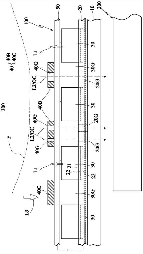
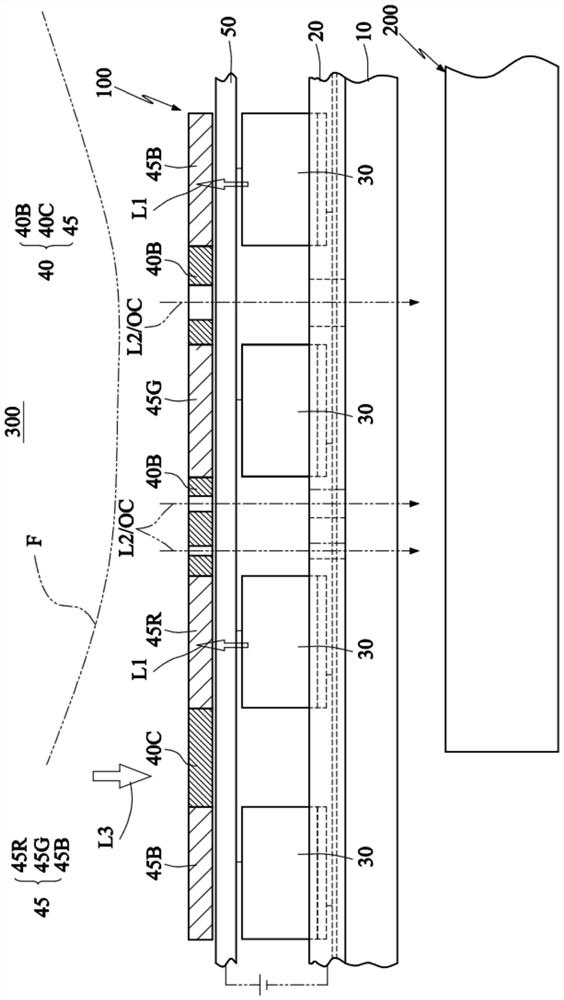
[0037] In order to solve the problem of the polarizer mentioned above, one solution is to remove the polarizer to reduce the loss of light in the optical path and provide a more energy-saving effect. When the polarizer above the OLED is removed, the anti-glare function becomes the main problem, so a filter layer (such as a black film layer) can be added to cover the exposed metal line area, greatly reducing the intensity of reflected glare. However, this will also significantly reduce the light transmittance of the OLED screen in the exposed metal line area (e.g., less than 1% or close to 0%), which will limit the optical under-screen sensing, which includes optical biometric (face shape, fingerprint, finger vein, blood oxygen, heartbeat heart rate, iris, etc.) sensors and other optical sensors, such as proximity sensors, ambient light sensors (Ambient Light) set under the screen Sensor), or even a camera, and so on. Therefore, it is necessary to further design and plan the metal ...


PUM


Abstract

An optical sensing device includes: a substrate; the circuit wiring layer is positioned on the substrate; a plurality of light emitting units arranged on the circuit wiring layer and used for emitting light; the light filtering layer is provided with a plurality of first light blocking parts which are respectively arranged above the plurality of pixel gaps among the plurality of light emitting units, and is provided with a plurality of light holes, the plurality of light holes are aligned with the plurality of light transmitting gaps of the circuit wiring layer, and the size of each light hole is smaller than or equal to the size of one corresponding light transmitting gap of the plurality of light transmitting gaps; and the optical sensor is arranged below the substrate and is used for executing under-screen optical sensing without a polaroid.

Description

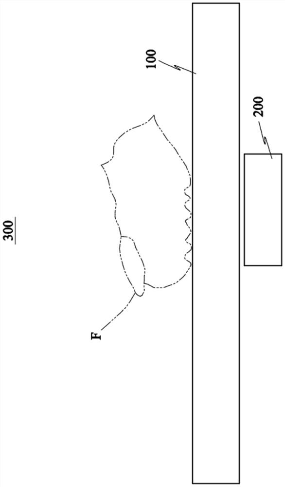
Technical field [0001] The present invention is about an optical sensing device, and in particular with respect to an optical sensing apparatus using a polarizer-free display panel. Background [0002] For example, mobile electronic devices such as mobile phones, tablets, laptops, etc. are usually equipped with user biometric systems, including different sensing technologies such as fingerprints, face shapes, irises, etc., to protect personal data security, which are used for portable devices such as mobile phones or smart watches, and also have the function of mobile payment, for user biometrics is to become a standard function, and mobile phones and other portable devices are more towards the trend of full screen or ultra-narrow borders. As a result, the traditional capacitive fingerprint button can no longer be used, and instead is a miniaturized optical imaging device, some very similar to traditional camera modules, with complementary Metal-Oxide Semiconductor (CMOS) Image ...

Claims


Application Information

Patent Timeline
IPC IPC(8): G06V40/13
CPCG06V40/13G02B5/20H01L31/0232H01L27/146H10K59/8792
Inventor 周正三范成至
Owner EGIS TECH
Learn More