Automatic spring tubing device and system

A tube loading and automatic technology, applied in the direction of measuring devices, reducing greenhouse gases, instruments, etc., can solve the problems of inability to guarantee the quality stability of cladding tubes, inconsistent compression lengths of compression springs, and different pressing forces of fuel pellets, etc.

Pending Publication Date: 2022-05-13
CHINA NUCLEAR POWER ENG CO LTD
View PDF0 Cites 0 Cited by
  • Summary
  • Abstract
  • Description
  • Claims
  • Application Information

AI Technical Summary

Problems solved by technology

[0003] In the prior art, the compressed length of the compression spring after being fed into the cladding tube cannot be accurately controlled, so that the compressed lengths of the compression springs in different cladding tubes are inconsistent, and thus the pressing force of the spring on the fuel pellet is different. Unable to guarantee the stability of cladding tube quality

Method used


Image

  • Automatic spring tubing device and system
  • Automatic spring tubing device and system
  • Automatic spring tubing device and system

Examples


Embodiment 1

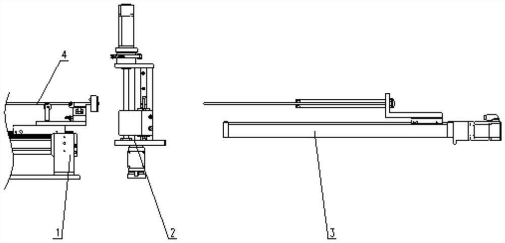
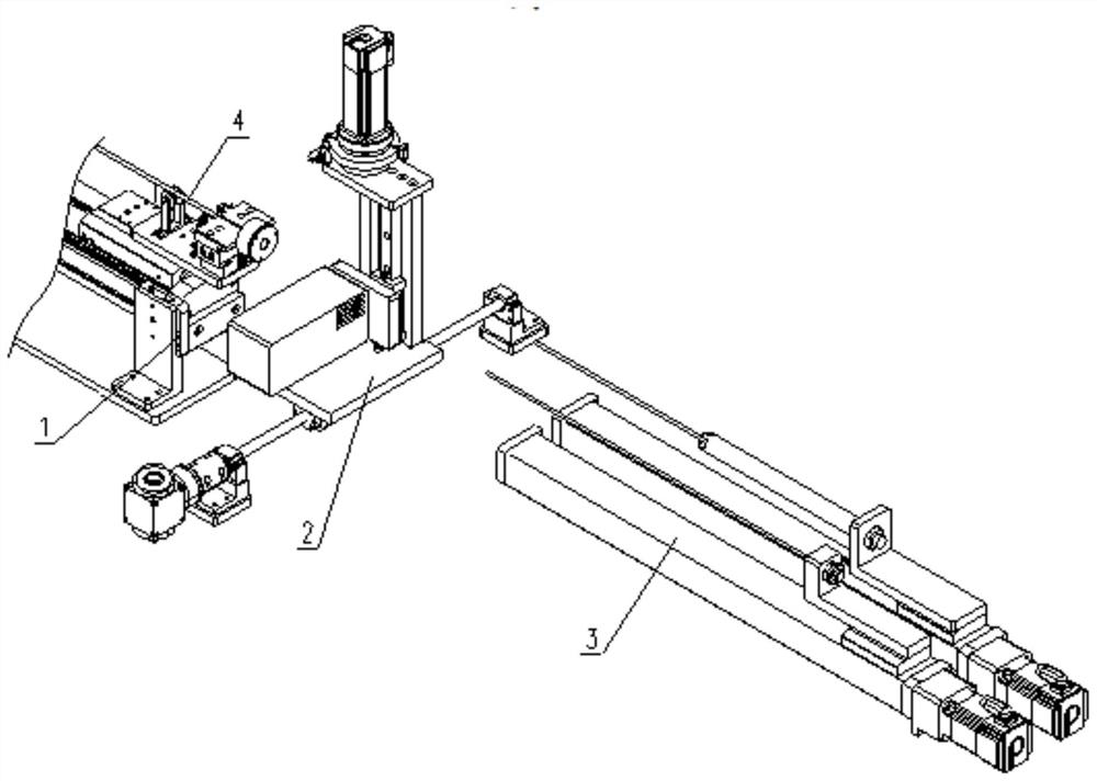
[0030] Such as figure 1 As shown, the present invention discloses a spring automatic tube loading device, which includes a tube loading mechanism 1, a material storage mechanism 2 and a push mechanism 3, the material storage mechanism 2 is used to store a compressed spring, and the diameter of the outer ring of the compressed spring is larger than that of the cladding tube 4 , so that after the compression spring is loaded into the cladding tube 4, the outer ring of the compression spring can generate a large enough friction force with the inner wall of the cladding tube 4, thereby compressing the pellet in the cladding tube 4.

[0031] Such as figure 1 , 2 As shown, the pushing mechanism 3 and the tube loading mechanism 1 are separately arranged on both sides of the storage mechanism 2, and the tube loading mechanism 1 is used to support and fix the cladding tube 4; the pushing mechanism 3 includes a push rod assembly and a measuring assembly.

[0032] Specifically, the measu...

Embodiment 2

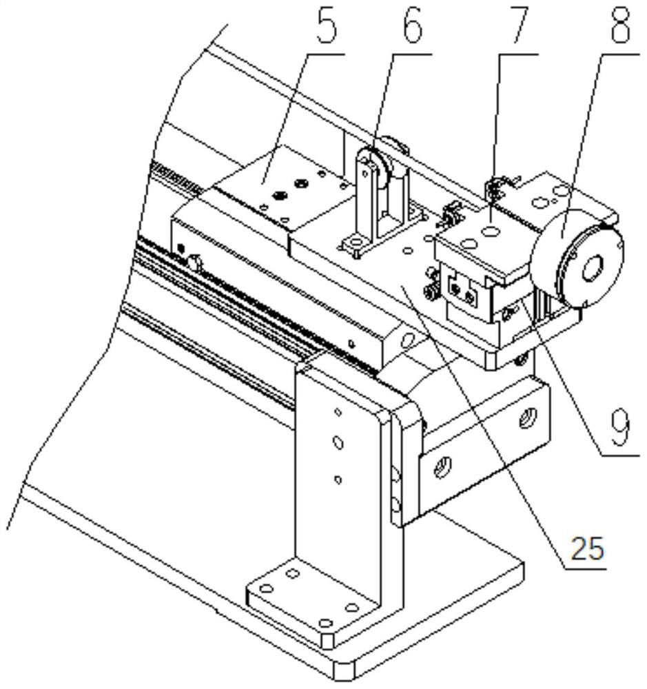
[0047] This embodiment discloses an automatic spring tube loading system, which includes a glove box, a positioning assembly, and the above-mentioned automatic spring tube loading device. The glove box is divided into three areas by three partition plates. The push mechanism 3, the material storage mechanism 2 and the tube loading mechanism 1 are successively arranged in three areas. The positioning assembly includes a positioning block 8. The center of the positioning block 8 is provided with a positioning hole. The positioning block 8 is installed between the storage mechanism 2 and the loading mechanism. The partition plate between the tube mechanisms 1, and the positioning hole communicates with the input end of the cladding tube 4.

[0048] Specifically, the material storage mechanism 2 is arranged in the middle area of ​​the three areas of the glove box, and the pushing mechanism 3 and the tube loading mechanism 1 are respectively arranged in two areas on both sides of th...


PUM


Abstract

The invention discloses an automatic spring tubing device and an automatic spring tubing system comprising the automatic spring tubing device, the automatic spring tubing device comprises a tubing mechanism, a storage mechanism and a pushing mechanism, the diameter of the outer ring of a compression spring is larger than the inner diameter of a cladding tube, and the pushing mechanism comprises a push rod assembly and a measuring assembly. The measuring assembly comprises a length measuring rod, the length measuring rod is used for measuring the first distance between the inlet end of the cladding tube and a core block in the cladding tube, the push rod assembly comprises a push rod, and the push rod is used for pushing one compression spring stored in the storage mechanism into the cladding tube after the length measuring rod measures the compression spring and making the compression spring located at the target position in the cladding tube. The length of the compression spring is set as a first length, the distance between the compression spring at the target position and the inlet end of the cladding tube is a second distance, and the second distance is equal to the difference value between the first distance and the first length. According to the device, the consistency of the pressing force of the springs in different cladding pipes on the core block can be ensured.

Description

technical field [0001] The invention belongs to the technical field of the nuclear industry, and in particular relates to an automatic spring tube loading device and an automatic spring tube loading system comprising the automatic spring tube loading device. Background technique [0002] MOX fuel rods used in fast neutron reactors contain fuel pellets and springs. The fuel pellets need to be closely arranged in the cladding tube, and there should be no random movement. In order to ensure the tightness and stability of the arrangement of the fuel pellets in the cladding tube, an interference spring is used to compress the fuel pellets. The resistance generated by the interference between the spring and the cladding tube ensures the pressing force of the spring on the fuel pellets. [0003] In the prior art, the compressed length of the compression spring after being fed into the cladding tube cannot be accurately controlled, so that the compressed lengths of the compression ...

Claims


Application Information

Patent Timeline
Patent Type & Authority Applications(China)
IPC IPC(8): G21C21/02G01B21/16
CPCG21C21/02G01B21/16Y02E30/30
Inventor 童晓东江保军翟家海顾寒芬
Owner CHINA NUCLEAR POWER ENG CO LTD
Why Eureka
Try Eureka