
Eureka
For R&D, Eureka makes reading and utilizing patents & technical documents easy.
Eureka AIR
Designed for self-driven R&D workflows. Generate viable solutions, solve complex R&D challenges, empower your innovation with AI.

Eureka Materials
Designed for material experts only. Revolutionize your material R&D, from search, analyze, to developing new materials.

TechResearch
Generate reliable direction feasibility study reports for your R&D in just a few steps.

TechSeek
Discover and master advanced knowledge NOW. Basics, ideas, possibilities, all at once.

TechMind
As an expert in R&D Theories, TechMind can generates customized viable solutions instantly.

TechRisk
Analyze your overall solution with one click, know your potential R&D risks in advance.

TechMonitor
Get weekly tech updates, stay abreast of the latest tech innovations and key insights.
Omnidirectional DTMB antenna
An antenna and axis technology, applied in the field of wireless electromagnetic wave signal receiving devices, can solve problems such as insulation performance decline, signal instability, plastic aging, etc., and achieve the effect of low cost and good receiving effect
- Summary
- Abstract
- Description
- Claims
- Application Information
AI Technical Summary
Problems solved by technology
Method used
Image

Examples
Embodiment 1
[0021] Embodiment 1, the present invention will be further described by taking Longkou Transmitting Station as an example below.
[0022] The digital TV terrestrial broadcast frequencies of the Longkou Transmitting Station are shown in the table below:
[0023]
[0024] As can be seen from the above table, there are two local frequency points in Longkou, namely f1=498, f2=514, substituting the formula ②f=(f1+f2+f3...+fn) / n to get the center frequency f=( 498+514) / 2=506MH Z ;
[0025] Substitute f into the formula ①λ=0.96×3×10 5 / f can get the center wavelength λ=0.96×3×10 of the received DTMB signal 5 / 506=569.17mm; where 0.96 is the wavelength correction factor.
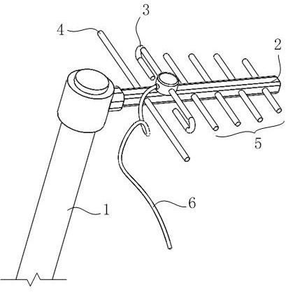
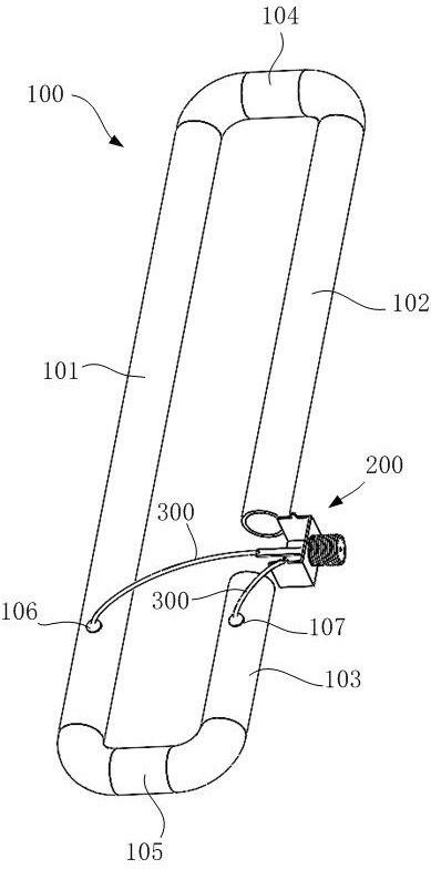
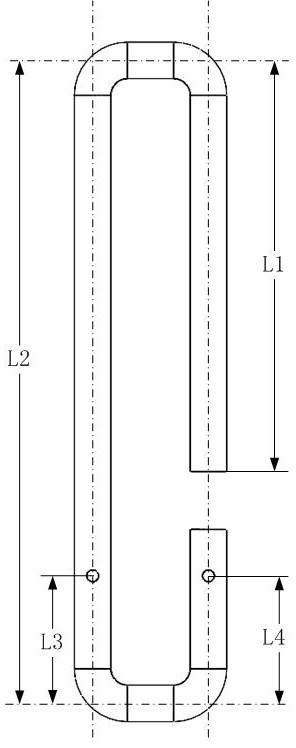
[0026] Such as Figure 2-3 An omnidirectional DTMB antenna as shown, includes a copper tube with an outer diameter of 6mm and a wall thickness of 0.5mm bent into a shape such as image 3 The shown C-shaped conductor 100, for convenience of explanation, divides the C-shaped conductor 100 into a body section ...
Embodiment 2
[0033] Embodiment 2, in order to better fix the C-shaped conductor 100, the coaxial cable connection base 200 and the wire 300, the inventor used an iron plate to make a rounded rectangular groove slightly larger than the C-shaped conductor 100. mold, a round hole with an inner diameter slightly larger than the outer diameter of the screw head of the coaxial cable connecting female seat 200 is opened on the side wall of the groove mold, and then the C-shaped conductor 100 is overhead placed in the groove mold, and the coaxial cable The screw head connecting the female seat 200 is exposed outside the side wall of the groove-shaped mould, through the round hole, and then the random copolymerized polypropylene particles are melted and poured into the groove-shaped mold, and the C-shaped conductor 100 and the coaxial cable are connected to the female seat 200 is completely buried, and the random copolymerized polypropylene is cooled to room temperature and taken out from the groove...
PUM
 Abstract
Description
Claims
Application Information
 - R&D Engineer
- R&D Manager
- IP Professional
- Industry Leading Data Capabilities
- Powerful AI technology
- Patent DNA Extraction
Browse by: Latest US Patents, China's latest patents, Technical Efficacy Thesaurus, Application Domain, Technology Topic, Popular Technical Reports.
© 2024 PatSnap. All rights reserved.Legal|Privacy policy|Modern Slavery Act Transparency Statement|Sitemap|About US| Contact US: help@patsnap.com