Ultralow-temperature protection device for high-voltage switch

A protection device, high-voltage switch technology, applied in the cooling/ventilation of substation/switchgear, board/panel/desk of substation/switchgear, substation/switch layout details, etc. Operation, difficult to install and fix, etc., to achieve the effect of improving ventilation

Pending Publication Date: 2022-05-13
赵锦华
View PDF1 Cites 0 Cited by
  • Summary
  • Abstract
  • Description
  • Claims
  • Application Information

AI Technical Summary

Problems solved by technology

[0004] The invention provides a high-voltage switch ultra-low temperature protection device, one of which is to have the functions of ventilation and low-temperature heating, and solve the problem that the high-voltage switch cannot operate normally in an ultra-low temperature environment; the other purpose is to solve the problem that it is not easy to install and fix and The problem that dust is easy to enter inside the switch, in order to achieve the effect of self-protection and fixed installation

Method used


Image

  • Ultralow-temperature protection device for high-voltage switch
  • Ultralow-temperature protection device for high-voltage switch
  • Ultralow-temperature protection device for high-voltage switch

Examples


Embodiment 1

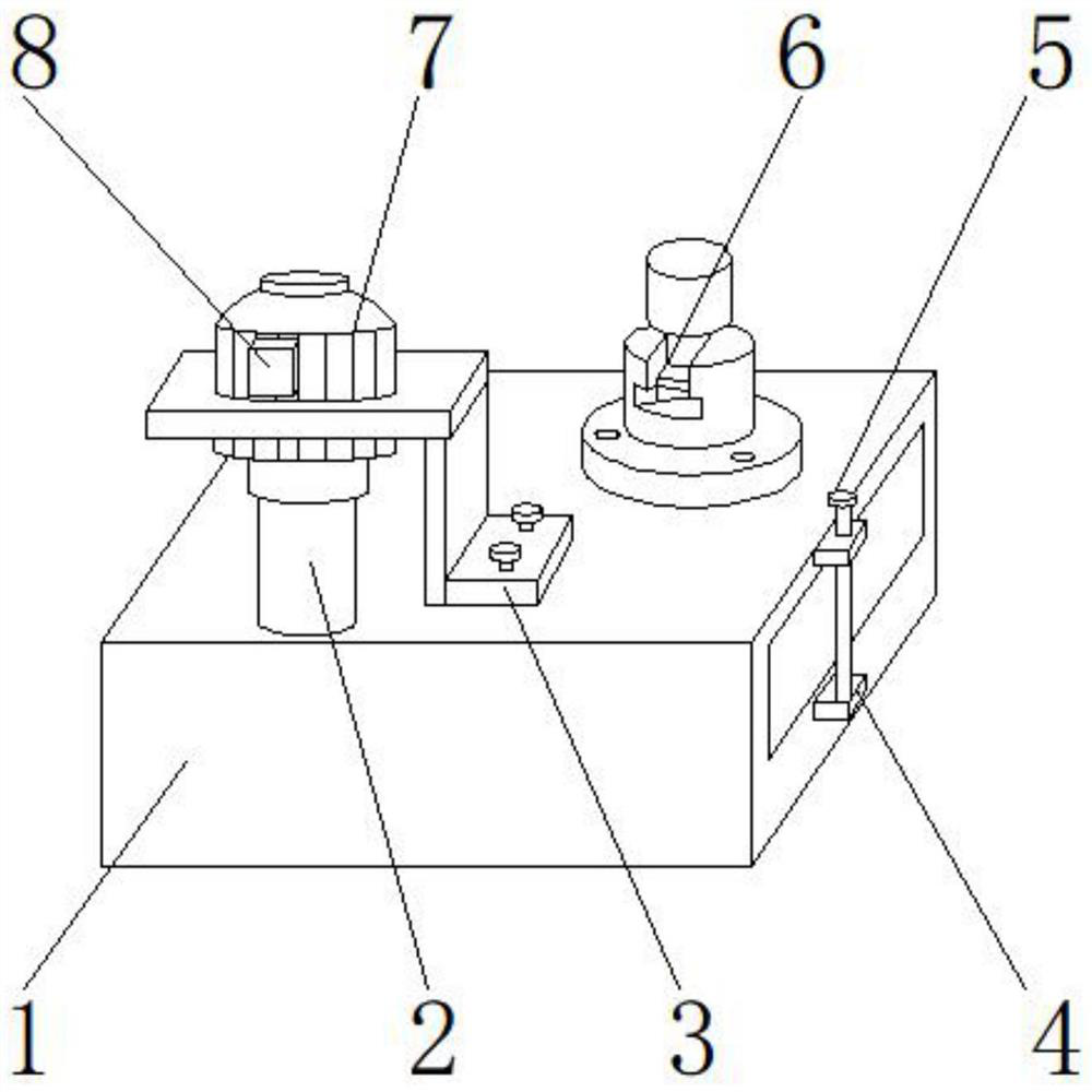
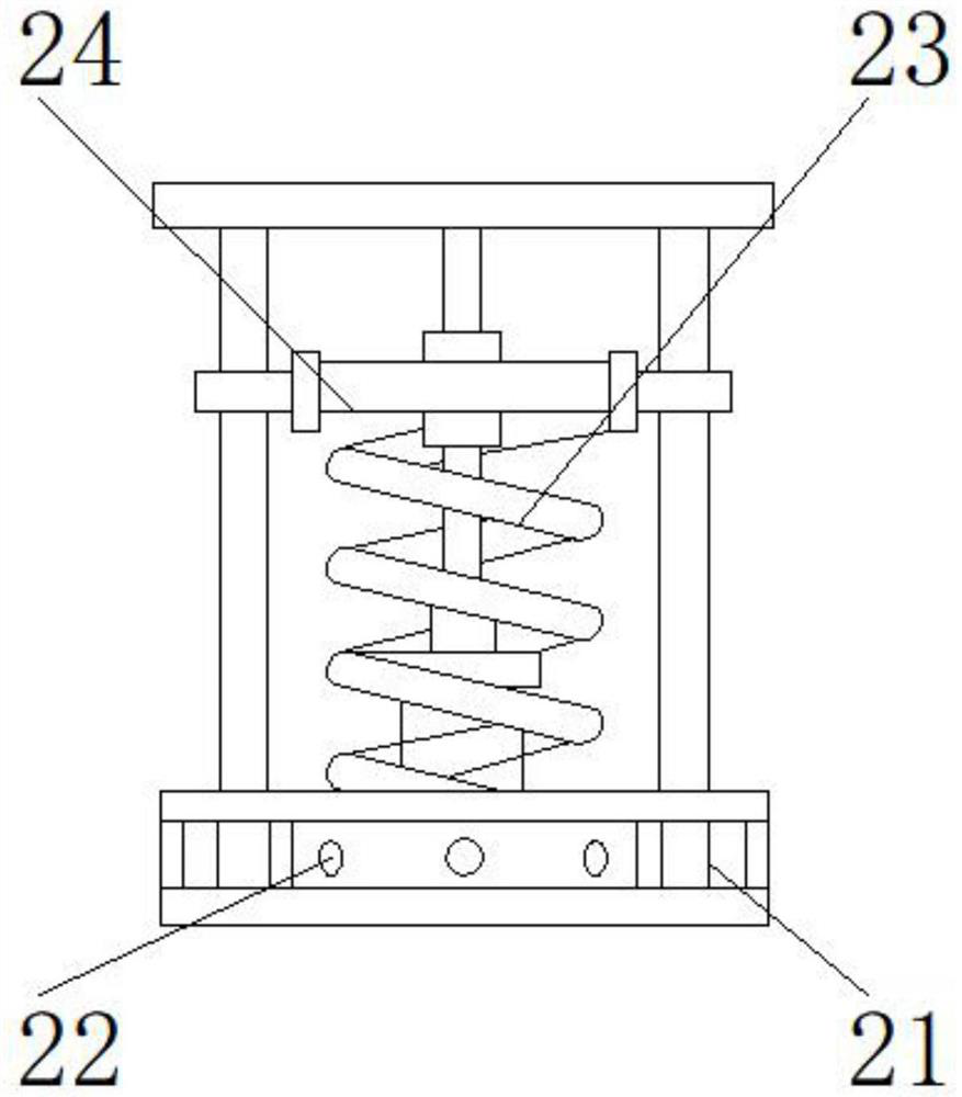
[0033] Such as Figure 1-8As shown, the present invention provides a high-voltage switch ultra-low temperature protection device, including a main body 1, the upper end of the main body 1 is provided with a ventilation device 2, the upper end of the ventilation device 2 is provided with an adjustment device 7, and the front end of the adjustment device 7 is provided with a controller 8 One side of the ventilation device 2 is provided with a protection device 3, one side of the protection device 3 is provided with a protection assembly 6, one side of the main body 1 is provided with a fixing device 5, and the lower part of the fixing device 5 is provided with an installation module 4; the ventilation device 2 comprises a chamber 21, a vent 22, a dust-proof net 23, and a dredging frame 24, the vent 22 is located at one side of the chamber 21, the dust-proof net 23 is positioned at the upper end of the vent 22, and the dredging frame 24 is positioned at the side of the dust-proof ...

Embodiment 2

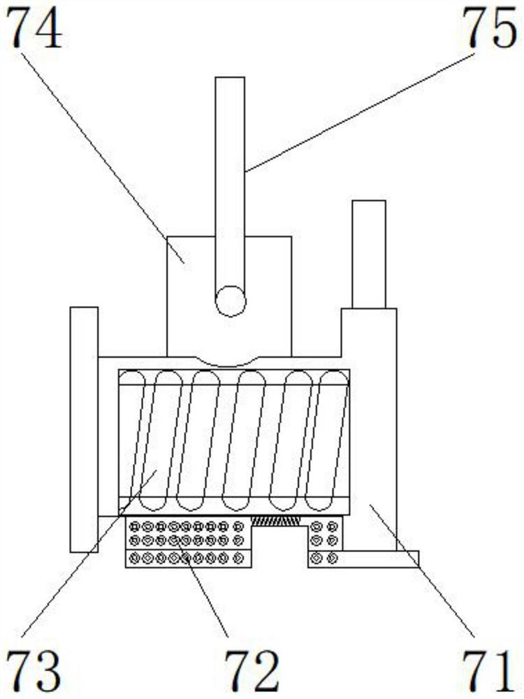
[0036] Such as Figure 1-8 As shown, on the basis of Embodiment 1, the present invention provides a technical solution: preferably, the adjustment device 7 includes a driving device 71, a translation block 72, a lead screw 73, a slider 74, a vertical shaft 75, and a lead screw 73 Located on one side of the drive unit 71, the translation block 72 is located at the lower end of the drive unit 71, the slide block 74 is located at the upper end of the lead screw 73, the vertical shaft 75 is located at the upper end of the slide block 74, and the vertical shaft 75 is arranged between the slide block 74. Threaded groove is arranged, and the lower end of vertical rotating shaft 75 is detachably connected with the lower end of slide block 74 by threaded groove, is provided with interface between leading screw 73 and driving device 71, and one side of leading screw 73 passes through interface and one of driving device 71 The side is fixedly connected, and a chute is provided between th...

Embodiment 3

[0039] Such as Figure 1-8 As shown, on the basis of Embodiment 1, the present invention provides a technical solution: preferably, the fixing device 5 includes a stud bolt 51, a trapezoidal pressure plate 52, a shoulder nut 53, a stepped support 54, and the trapezoidal pressure plate 52 is located at the double The upper end of the head bolt 51, the shoulder nut 53 is located at the upper end of the trapezoidal pressing plate 52, the stepped support 54 is located at one side of the trapezoidal pressing plate 52, a notch is arranged between the stud bolt 51 and the trapezoidal pressing plate 52, the upper end of the stud bolt 51 The lower end of the trapezoidal pressing plate 52 is detachably connected through the notch, and a welding block is arranged between the trapezoidal pressing plate 52 and the stepped support 54. One side of the trapezoidal pressing plate 52 is fixedly connected with one side of the stepped support 54 through the welding block, and the trapezoidal press...


PUM


Abstract

The invention discloses a high-voltage switch ultralow-temperature protection device, and relates to the technical field of electric power, and the high-voltage switch ultralow-temperature protection device comprises a main body, the upper end of the main body is provided with a ventilation device, the upper end of the ventilation device is provided with an adjusting device, the front end of the adjusting device is provided with a controller, and one side of the ventilation device is provided with a protection device. A protection assembly is arranged on one side of the protection device. Under the combined action of the fixing band, the electric tracing band, the stainless steel band, the heat preservation material, the heating box, the heat conduction pipe, the heating wire and the temperature sensor, the high-voltage switch can normally operate in an ultralow-temperature environment and cannot be affected by temperature, a protective layer is additionally arranged on the surface of the high-voltage switch, the insulation effect can be achieved, and the service life of the high-voltage switch is prolonged. And cold air is prevented from entering the high-voltage switch, the lead screw rotates to drive the translation block on the lower portion to be far away, so that the ventilation opening is opened, and along with rotation of the vertical rotating shaft, air enters the ventilation opening, passes through the ventilation cavity and is discharged towards the cavity, and air circulation is accelerated.

Description

technical field [0001] The invention relates to the field of electric power technology, in particular to an ultra-low temperature protection device for a high-voltage switch. Background technique [0002] High-voltage switch refers to the power generation, transmission, distribution or power conversion of the power system. It is usually installed in a high-voltage switchgear. The switchgear has functions such as overhead incoming and outgoing lines, cable incoming and outgoing lines, and bus connection. , metallurgy and steel rolling, light industry textile and residential quarters, high-rise buildings and other places. [0003] At present, the existing ultra-low temperature protection devices for high-voltage switches on the market are mainly improved for the damage of high-voltage switch insulation. For example, a kind of ultra-low temperature protection device for high-voltage switches provided by Chinese patent CN202797741 U has the ability to prevent the insulation gas ...

Claims


Application Information

Patent Timeline
IPC IPC(8): H02B1/56H02B1/28H02B1/04H02B1/32
CPCH02B1/565H02B1/28H02B1/04H02B1/32
Inventor 赵锦华
Owner 赵锦华
Why Eureka
Try Eureka