Supercharge Your Innovation With Domain-Expert AI Agents!

High-load photovoltaic support profile

A photovoltaic support and high-load technology, applied in the support structure of photovoltaic modules, photovoltaic power generation, photovoltaic modules, etc., can solve the inconvenience of flexibly adjusting the height and angle of photovoltaic panel support, inconvenient handling and installation, inconvenient installation and assembly, etc. problems, to achieve the effect of convenient handling and installation, maintaining stability, and convenient disassembly

Inactive Publication Date: 2022-05-13
江阴市刚宇金属制品有限公司
View PDF0 Cites 0 Cited by
  • Summary
  • Abstract
  • Description
  • Claims
  • Application Information

AI Technical Summary

Problems solved by technology

[0003] The existing technology has the following disadvantages: the existing high-load photovoltaic support profiles have high technical requirements for operators during installation. During installation, it is necessary to measure the front and rear height dimensions of the high-load photovoltaic support profiles, which is inconvenient to flexibly adjust the photovoltaic panels. The height and angle of the bracket require a lot of disassembly and assembly work, which is inconvenient for installation and assembly. After the photovoltaic panel is installed, the load requirements on the profile of the photovoltaic support are relatively high. Traditional photovoltaic support profiles generally use solid profiles, and the consumption of multiple materials is high. At the same time, its own quality is relatively large, which is inconvenient to carry and install. The profiles with ordinary hollow structures are used for a long time, and deformation occurs.

Method used


Image

  • High-load photovoltaic support profile
  • High-load photovoltaic support profile
  • High-load photovoltaic support profile

Examples


Embodiment Construction

[0029] The preferred embodiments of the present invention will be described below in conjunction with the accompanying drawings. It should be understood that the preferred embodiments described here are only used to illustrate and explain the present invention, and are not intended to limit the present invention.

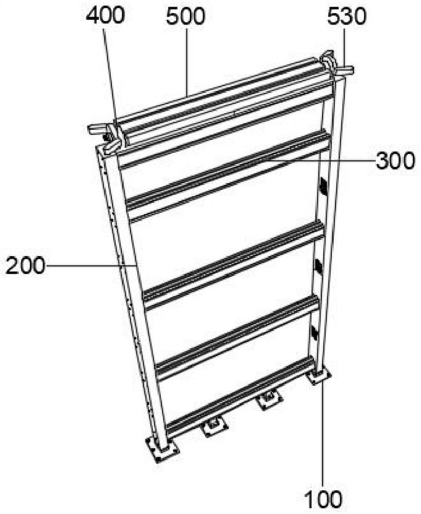
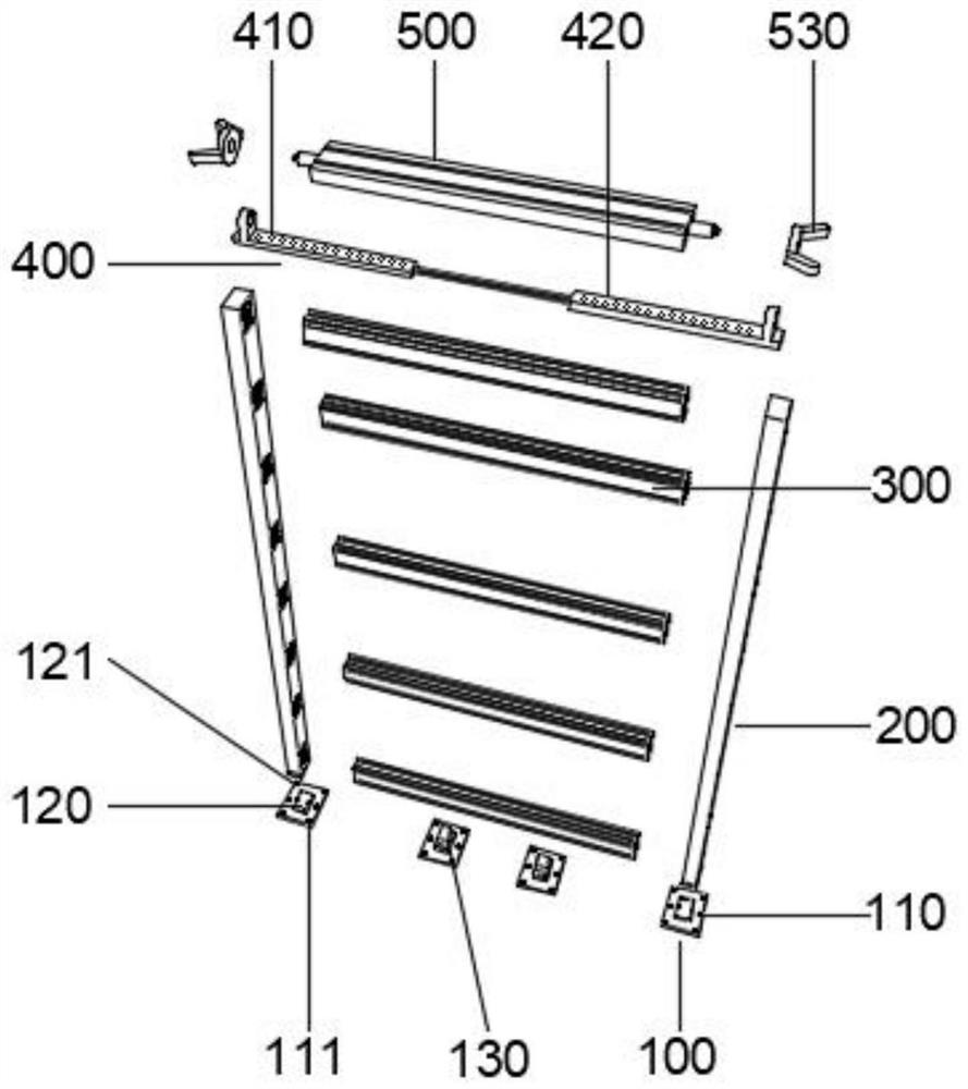
[0030] Refer to attached Figure 1-8, the high-load photovoltaic support profiles provided by the present invention, in order to achieve the above object, the present invention provides the following technical solutions: high-load photovoltaic support profiles, including a base 100, the base 100 is provided with four groups, and the top of the base is fixedly installed with poles 200, poles Two groups are symmetrically arranged around 200. The two groups of vertical rods 200 are evenly fixed and installed with a cross bar 300, and the top cross bar 300 is fixed with a connecting frame 400 on the top. The outer wall of the connecting frame 400 is rotatably connected t...


PUM


Abstract

The invention discloses a high-load photovoltaic support profile, and relates to the technical field of photovoltaic support profiles, and the technical scheme is that the high-load photovoltaic support profile comprises four groups of bases, two groups of vertical rods are fixedly mounted at the tops of the bases in a bilateral symmetry manner, and cross rods are uniformly and fixedly mounted between the two groups of vertical rods; a connecting frame is fixedly mounted at the top of the cross rod at the top, a mounting frame is rotatably connected to the outer wall of the connecting frame, the cross rod is of an integrated structure, third bolt holes are uniformly formed in the center of the top of the cross rod, and two groups of sliding grooves are formed in the top of the cross rod in a bilateral symmetry mode. According to the photovoltaic panel, the vertical rods are arranged, the through holes are formed in the surfaces of the vertical rods, the cross rods are inserted into the vertical rods, the insertion hole positions can be flexibly adjusted according to the height of the photovoltaic panel, an operator can rapidly complete insertion between the cross rods and the vertical rods conveniently, meanwhile, the insertion stability is kept, the bearing performance of the vertical rods is improved, and meanwhile the operator can conveniently conduct installation.

Description

technical field [0001] The invention relates to the technical field of photovoltaic support profiles, in particular to high-load photovoltaic support profiles. Background technique [0002] Photovoltaic is the abbreviation of solar photovoltaic power generation system. It is a new type of power generation system that uses the photovoltaic effect of solar cell semiconductor materials to directly convert solar radiation energy into electrical energy. There are two modes of independent operation and grid-connected operation. At the same time, The classification of solar photovoltaic power generation systems, one is centralized, such as the large northwest ground photovoltaic power generation system. Solar energy is converted into electrical energy for use by electrical equipment. Generally, it is necessary to set up high-load photovoltaic support profiles to install photovoltaic panels, so that the photovoltaic panels have good lighting effects and improve the efficiency of ele...

Claims


Application Information

Patent Timeline
Patent Type & Authority Applications(China)
IPC IPC(8): H02S20/00H02S20/30F24S25/10F24S25/63
CPCH02S20/00H02S20/30F24S25/10F24S25/63Y02E10/47Y02E10/50
Inventor 曹瑜朱林刚
Owner 江阴市刚宇金属制品有限公司
Features
  • R&D
  • Intellectual Property
  • Life Sciences
  • Materials
  • Tech Scout
  • Unparalleled Data Quality
  • Higher Quality Content
  • 60% Fewer Hallucinations
Learn More