
Automatic rubber tapping machine and control method thereof

A glue machine and automatic technology, applied in agriculture, forestry, application, etc., can solve the problems of less hang-up, less installed machines, and impact on production, and achieve the effect of fast rubber tapping, durable cutter heads, and easy replacement

Pending Publication Date: 2022-05-17
黄伟
View PDF12 Cites 0 Cited by
  • Summary
  • Abstract
  • Description
  • Claims
  • Application Information

AI Technical Summary

Problems solved by technology

[0010] Although a tree and a smart bionic rubber tapping machine currently on the market solve various problems of manual rubber tapping, due to the use of bionic artificial blades for tapping rubber, the operation requires a large The driving force and rubber tapping method are relatively simple, and the mechanical coordination of the whole machine is relatively complicated. The whole machine needs to be dismantled during maintenance, and the machine cost is relatively high. The on-hook requirements are relatively high, and the actual on-hook amount per acre of rubber forest land is relatively small, resulting in high costs and difficult promotion
[0011] The currently disclosed Chinese invention patent application CN104429813A, Chinese invention patent application CN106034980A, and Chinese invention patent application CN106718653A all use bionic artificial blades to tap rubber, and the rubber tapping mode is relatively single. When the blade taps rubber, it needs a large operating driving force to cut off the bark, which has relatively high requirements for the drive of the whole machine. It is easy to jam the knife when encountering tree tumors and depressions. In serious cases, it is easy to cause damage to the rubber tapping machine, and in light cases, it may cause missing cuts and affect the output. , it is often necessary to choose a good-looking rubber tree to install the machine. In fact, the amount of rubber trees that can be installed with machines is relatively small.
[0012] Chinese invention patent application CN111972250A adopts a double helix rail up and down in parallel layout, and the vertical tool post assembly motor driven screw rod connected in the middle drives the upper and lower driving gears along the Running in the upper and lower parallel spiral tracks, it drives the knife holder assembly to complete the horizontal tapping and vertical line change. Due to the use of the upper and lower parallel double spiral tracks, it will occupy a part of the rubber tapping range when fixed with straps. The upper and lower double spirals The parallel layout of the rails not only increases the manufacturing cost, but also increases the parallel installation of the double helix rails and the requirements for hanging the rubber tree. The rails and the tool holder assembly are integrated, and the whole machine needs to be dismantled during maintenance, which cannot be quickly repaired on site.
[0013] Although the Chinese patent application CN109924100A adopts the electric rotary cutting disc blade, due to the large diameter of the rotary blade disc surface, it cannot be touched when encountering a depression and cannot be cut.
[0014] The above invention uses binding straps to fix the machine. Although it does not hurt the rubber tree, the stability is poor. The quality of the binding straps determines the firmness and service life of the whole machine. Invisibly added some costs
Moreover, the above invention applications require complex mechanical gear coordination between the components, and the integration is relatively large. After each component has a problem, the whole machine needs to be dismantled and maintained, and it cannot be replaced on site, resulting in high operation and maintenance costs. Large-scale promotion and use

Method used


Image

  • Automatic rubber tapping machine and control method thereof
  • Automatic rubber tapping machine and control method thereof
  • Automatic rubber tapping machine and control method thereof

Examples


Embodiment Construction

[0059] The present invention will be further described in detail below in conjunction with the accompanying drawings and embodiments.

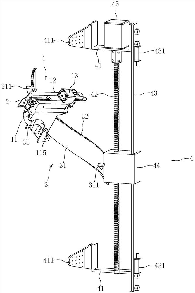
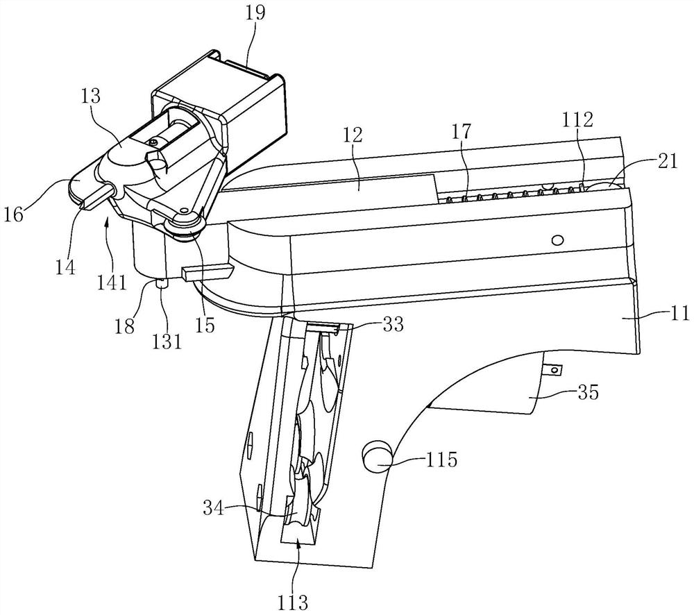
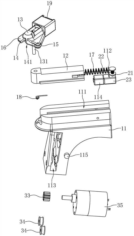
[0060] like Figure 1 to Figure 4 Shown is a preferred embodiment of the automatic rubber tapping machine of the present invention. The automatic rubber tapping machine includes a cutter assembly 1, a limit assembly 2, a first drive mechanism 3 and a second drive mechanism 4, the cutter assembly 1 is used to cut the rubber tree, and the first drive mechanism 3 is used to drive the cutter assembly 1 to spiral around the rubber tree shape rotation, the second drive mechanism 4 is used to drive the cutter assembly 1 up and down. The whole machine adopts a modular combination method so that all parts can be quickly disassembled, and the problematic parts can be quickly replaced to reduce the time for disassembly and maintenance.

[0061] Wherein, the cutter assembly 1 includes a cutter holder 11, a sliding arm 12, a rotating seat 13, a cutter he...


PUM


Abstract

The invention discloses an automatic rubber tapping machine which comprises a cutter assembly (1) and a first driving mechanism (3), and is characterized in that the cutter assembly (1) comprises a cutter rest (11) provided with a sliding groove (111); at least part of the sliding arm (12) is inserted into the sliding groove (111); the rotating seat (13) is rotatably mounted on the sliding arm (12); the tool bit (14), the guide piece (15) and the tool depth limiting guide plate (16) are all located on the rotating seat (13); the first elastic piece (17) can enable the sliding arm (12) to always have a trend of moving close to the rubber tree; and the second elastic piece (18) can enable the guide piece (15) positioned on the rotating seat (13) to always have a trend of abutting against the rubber tree. The invention further discloses a control method of the automatic rubber tapping machine. Compared with the prior art, the automatic rubber tapping machine is stable in channel cutting and capable of avoiding tool clamping.

Description

technical field [0001] The invention relates to the technical field of rubber tapping of agricultural machinery in the natural rubber industry, in particular to an automatic rubber tapping machine and a control method thereof. Background technique [0002] The economic benefits of rubber trees come from the latex output obtained from rubber tapping, and natural rubber is an important equipment material in various countries. How to extract latex from rubber trees simply and efficiently has always been an urgent problem for the rubber industry. Rubber trees can be tapped continuously for 30 to 40 years from planting to meeting the cutting requirements, and natural rubber is obtained by cutting the milk ducts in the bark of rubber trees. [0003] From the earliest method of using sharp tools to cut rubber trees to remove rubber to obtain latex, it was not until 1897 that the director of the Singapore Botanic Garden, Huang Dele, invented the rubber tree continuous rubber tapping...

Claims


Application Information

Patent Timeline
IPC IPC(8): A01G23/12
CPCA01G23/12
Inventor 黄大伟
Owner 黄伟
Learn More