Robot arm of automatic pipetting system

A robot arm and pipetting technology, applied to the support of burettes/pipettes, laboratory containers, instruments, etc., can solve the problems of short life cycle, high mechanical resistance, unsuitable structure, etc., and achieve compactness Space, compact design, space-saving effect

Pending Publication Date: 2022-05-17
帝肯贸易股份公司
View PDF5 Cites 0 Cited by
  • Summary
  • Abstract
  • Description
  • Claims
  • Application Information

AI Technical Summary

Problems solved by technology

Even though these switches offer improved switching action, their mechanical resistance is still too high, their life cycle is too short for many ro

Method used


Image

  • Robot arm of automatic pipetting system
  • Robot arm of automatic pipetting system
  • Robot arm of automatic pipetting system

Examples


Embodiment Construction

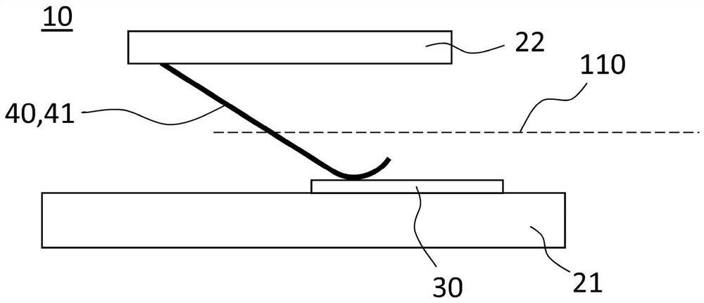
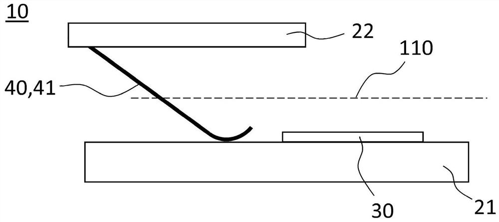
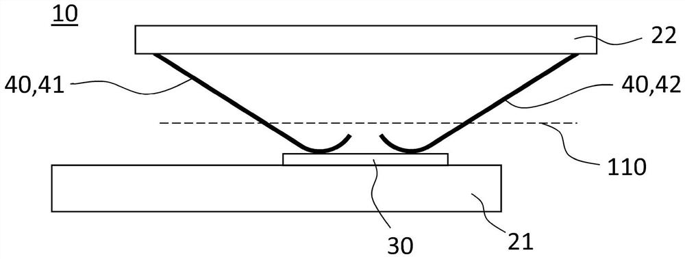
[0056] Figure 1a A schematic diagram showing a full cross-section of the slide switch 10 according to the invention in a first position.

[0057] The slide switch 10 shown here comprises a first support member 21 and a second support member 22 configured to slide relative to each other between a first position and a second position along a movement axis 110 shown in phantom. A terminal 40 in the form of a resilient and inherently stable first wiping member 41 is physically attached to said second support member 22 and is in physical and electrical contact with the conductive contact pad 30 when the slide switch 10 is in the first position shown. . The purpose of the second support member 22 is to hold the first wiper member 41 in place and at a uniform distance from the first support member 21 . The contact pad 30 must be at least superficially conductive so that current can flow between the first wiping member 41 and the contact pad 30 when the support members 21 , 22 are i...


PUM


Abstract

A robotic arm of an automated pipetting system, comprising: a pipetting tip adapter; a slide switch that detects the presence of a pipette tip on a pipette tip adapter includes: first and second supports that slide relative to each other along an axis of movement between first and second positions; a conductive contact pad arranged on the first support; an electrically conductive terminal attached in physical contact to the second support when the support is in the first position, the terminal being an elastic and internally stable first wiping member extending along the axis of movement, the first wiping member being not in physical contact with the contact pad when the support is in the second position, and the second wiping member being not in physical contact with the contact pad when the support is in the first position. A current can flow between the first wiper and the contact pad when the support is in the first position, and the current between the wiper and the contact pad is interrupted when the support is in the second position. The use of a robotic arm in an automated pipetting system, a slide switch detects the presence of a pipetting tip on a tip adapter. An automated pipetting system includes a robotic arm that detects the presence of a pipetting tip on a tip adapter.

Description

technical field [0001] The invention relates to a robotic arm of an automated pipetting system comprising a pipette tip adapter and a slide switch for detecting the presence of a pipette tip on said adapter. Background technique [0002] Electrical switches are common and can be found in household appliances, automobiles, and basically any electrical device. There are many different types of electrical switches in use, the most common being electromechanical devices comprising one or more sets of movable electrical contacts which, when in contact, allow electrical current to pass between them. Many specialized forms exist to meet specific needs. In robotics, switches are often used as sensing elements to detect fluid levels, pressure, temperature or the position of mechanical parts. Such switches need to be small and meet high requirements with regard to service life. Reed switches have been widely used as sensing elements in robotics. They are actuated by electromagneti...

Claims


Application Information

Patent Timeline
IPC IPC(8): B01L3/02B25J11/00
CPCB01L3/021B25J11/00B01L3/0275G01N2035/103G01N2035/1013G01N35/10B01L3/0279B01L2200/143H01H3/16H01H1/36H01H1/365H01H1/403B01L9/54B01L2300/0645B01L2300/0663B01L2300/12B01L2300/123B01L2300/126B25J18/00G01N35/0099
Inventor T·盖格斯
Owner 帝肯贸易股份公司
Why Eureka
Try Eureka